


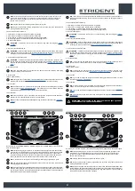
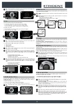
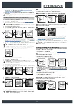
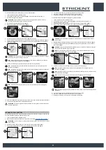
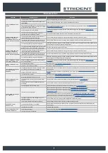
4. Press the drive pedal (4) to begin moving the machine (
Fig. 3
).
N.B. :
if the button (2) is pressed when working in ECO-MODE, the machine will shift to
MANUAL MODE, leaving the program in use at the time active (
Fig.4
).
N.B. :
if the "ZONE" button (4) is pressed when working in ECO-MODE, the machine will shift
to PROGRAM ZONE mode (
Fig.2
); as soon as button (4) is pressed, the screen enabling you
to select the working zone will appear on the display (
Fig.5
).
MANUAL
0000.00
100%
4
3
4
Warehouse
Canteen
Office
Reception
Exit
SELEZIONE ZONE
0000.00
100%
5
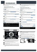
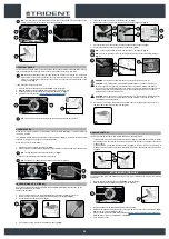
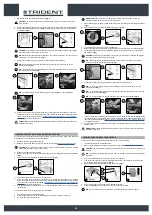
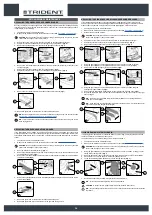
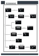
MANUAL MODE
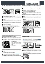
To activate the MANUAL-MODE program, proceed as follows:
1. Sit on the driver’s seat.
2. Insert the key (1) into the main switch on the control panel. Set the main switch to "I" (
Fig.1
).
3. Using the DS selector (2), select the working program you want; see “
” (
Fig.2
).
N.B. :
by selecting one of the three working programs on the DS selector, ECO-MODE will be
automatically activated.
4. Deactivate ECO-MODE by pressing the button (3) at the centre of the DS selector (
Fig.2
); the
display will move from ECO-MODE (
Fig.2
) to MANUAL MODE (
Fig.3
).
N.B.
: the grey ECO-MODE key means that the eco mode is not active. A green ECO-MODE
key means that economic mode is active. In addition, when ECO-MODE is not active, on the
text indicator row (4) on the display, the word "MANUAL” will appear (
Fig.2
).
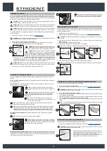
5. Press the drive pedal (5) to begin moving the machine (
Fig. 4
).
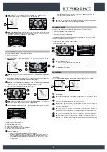
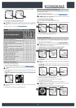
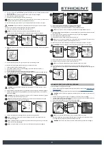
N.B. :
if the button (3) (
Fig.2
)is pressed when working in MANUAL MODE, the machine will
shift to ECO-MODE, leaving the program in use at the time active.
N.B. :
if the "ZONE" button (6) is pressed when working in MANUAL MODE, the machine will
shift to PROGRAM ZONE mode; as soon as button (6) is pressed, the screen enabling you to
select the working zone will appear on the display (
Fig.5
).
In manual mode the visible buttons are:
A. Adjusting the detergent solution.
B. Vacuum motor performance level.
C. Pressure level exercised on the central brush head.
D. Maximum forward movement speed level.
N.B.
: the four keys are always present but can be selected depending on the working mode
selected. Particularly:
•
Transfer: the visible button will be that of the maximum speed.
•
Scrubbing without drying: the buttons visible will be those of the maximum speed, the
detergent solution adjustment and the pressure exercised on the central brush head.
•
Drying: the buttons visible will be those of the maximum speed and the vacuum motor
performance level.
ECO mode
0000.00
100%
3
2
4
6
2
1
1
ON
MANUAL
0000.00
100%
3
D
A
C
B
4
5
Warehouse
Canteen
Office
Reception
Exit
SELEZIONE ZONE
0000.00
100%
5
•
Scrubbing with drying: the buttons visible will be those of the maximum speed, the
detergent solution adjustment, the pressure exercised on the central brush head and
performance level of the vacuum motor.
N.B.
: the disabled buttons and the respective indicators are grey.
N.B.
: each time one of the enabled keys is pressed, it increases the relative level in a cyclical
manner. Only the detergent solution adjustment permits zero level.
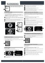
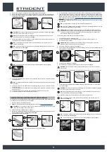
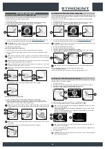
PROGRAM ZONE MODE
The zone programs are programs saved in the machine's memory, the parameter levels:
•
Pressure exercised on the central brush head
•
Forward speed
•
Adjustment of the detergent solution flow
•
Vacuum motor efficiency
they are fixed and have been created based on the type of environment in which you want to work.
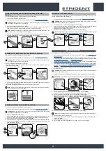
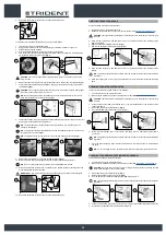
To select one of the zone programs, do as follows:
1. From any screen, press the “ZONE” button (1) (
Fig.1
).
2. As soon as the button (1) is pressed, the “ZONE SELECTION” menu will be displayed (
Fig.2
).
Select one of the programs.
N.B.
: the name of the zone program selected is displayed in the
text indicator (3)
(
Fig.1
).
N.B.
: to exit the zone program:
•
From the zone program menu select the “EXIT” key
•
Enable and then disable the ECO-MODE key.
N.B.
: the light blue ZONE key shows that the selected zone is active, in this case the
ECO-MODE button is not active.
MANUAL
0000.00
100%
Warehouse
Canteen
Office
Reception
Exit
SELEZIONE ZONE
0000.00
100%
1
2
1
3
2
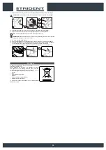
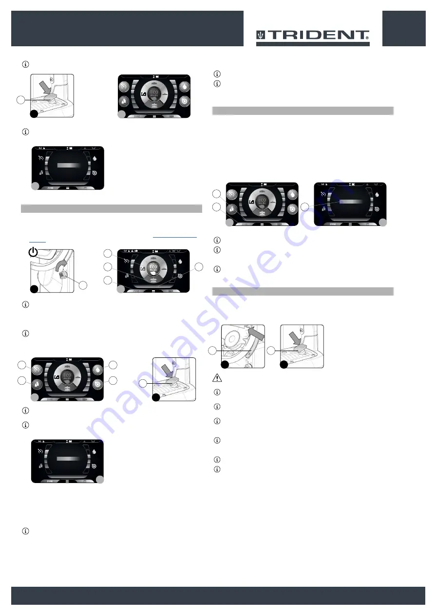
REVERSE GEAR
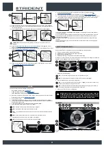
This machine is equipped with electronic traction control. To reverse, proceed as follows:
1. Engage the “REVERSE GEAR ACTIVATION/DEACTIVATION” lever (1) underneath the steering
wheel (
Fig.1
).
2. Press the drive pedal (2) (
Fig.2
); in this manner the machine will begin to move in reverse.
CAUTION
: the reverse speed is lower than the forward speed to comply with current health and
safety standards.
N.B.
: In order to disengage the reverse gear, disengage the lever (1) underneath the steering
wheel (
Fig.1
).
NB
: Once the lever has been engaged (1), the acoustic signalling device will be activated in
order to signal that the machine's reverse gear has been engaged.
NB
: If the reverse gear is engaged with the squeegee in its working position, once the drive
pedal is pressed, the machine will begin to move in reverse and the squeegee body will be
raised into its resting position.
N.B.
: If the reverse gear is engaged with the brush head in its working position, once the drive
pedal is pressed, the machine will begin to move in reverse and the brush head will remain in its
working position, but the solenoid valve will stop dispensing detergent solution to the brushes.
N.B.
: if you reverse with the video camera accessory (optional), the image is shown full screen.
N.B.
: if you reverse using the anti-collision system (optional) a special function activates that
manages the ON/OFF frequency of the buzzer. Every 50ms a trigger signal is sent to the
ultrasound sensor, the sensor returns a signal that remains active for a period that is inversely
proportional to the distance of the reflecting object.
2
1
1
2
23


