


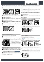
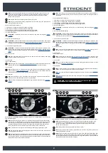
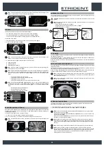
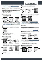
BUZZER
The machine is equipped with a buzzer. if you need to sound a warning,
just press the button (1) on the steering column (
Fig.1
).
1
1
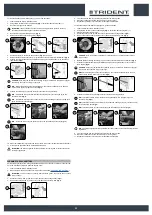
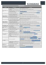
EXTRA BRUSH HEAD PRESSURE
This machine is capable of increasing the pressure exerted upon the brushes during the work cycle.
This can be done in the following manner:
1.
Check that the brush head body is in contact with the floor, if not select in the DS selector the
programs “SCRUBBING WITH DRYING” OR “SCRUBBING WITHOUT DRYING” (
Fig.1
).
2. Engage the “EXTRA-PRESSURE ACTIVATION/DEACTIVATION” lever (1) underneath the steering
wheel (
Fig.2
).
3. Press the drive pedal (2) (
Fig.3
) to initiate the machine's working cycle.
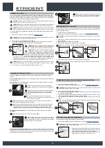
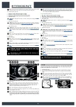
N.B.
: as soon as the lever (1) is shifted the control display will show the “POWER” screen
(
Fig.4
), in the middle of the screen there is a graphic symbol (3) and a numeric symbol (4), these
represent a countdown.
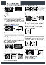
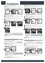
N.B.
: when the extra-pressure function is activated, the countdown starts. During this time, a
pressure stronger than the standard pressure is exerted on the brush head body.
N.B.
: at the end of the countdown you return to the working screen that was previously used and
the pressure on the brush head goes back to standard.
2
3
2
3
Back
0000.00
100%
POWER
0000.00
100%
1
4
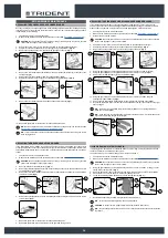
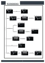
MAINTENANCE LIGHTS (OPTIONAL)
The machine has blinking lights to increase visibility of the parts that could require controlling by the
operator. The switch (1) on the front of the machine (
Fig. 1
) has three positions:
1. ON: the blinking lights are always on.
2. AUTO: the blinking lights come on only the relative inspection hatches are opened (e.g. recovery
tank).
3.
OFF: the blinking lights are always off.
1
1
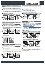
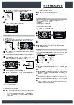
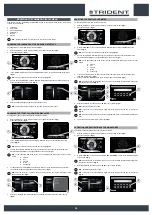
WORKING HEADLIGHTS
The machine is equipped with front and rear working lights.
To start them do as follows.
1. With the machine on, press the menu button (1) on the working screen (
Fig.1
).
2. Press the working lights activation - deactivation button (2) (
Fig.2
).
N.B.
: if the symbol (2) is grey the working lights are not active, if the symbol (2) is green the
working lights are active.
OFFICE
0000.00
100%
0000.00
100%
ECO mode
1
2
2
1
3
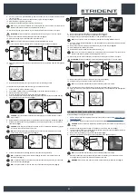
N.B.
: to quit the menu screen, wait a short time without pressing anything, or else press on any
point of the display (except one of the displayed buttons).
N.B.
: the sidelights come on when the machine is started.
N.B.
: if the side lights are activated the relative symbol (3) is displayed.
N.B.
: if you want to switch off the lights press the button (2).
N.B.
: to return to the working screen press on any point of the screen, except the edges of the
display or else wait three seconds without touching anything.
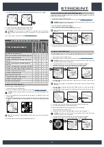
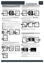
DETERGENT SOLUTION RECYCLING SYSTEM (OPTIONAL)
Upon request the machine can be fitted with a system that allows the detergent solution to be recycled
so that productivity can be increased, since the number of stops needed to empty and fill the tanks is
reduced. As a result less water and detergent are used, thereby making the operator safer, who comes
into contact with the chemical products less frequently, and the operation is more environmentally
friendly.
To start it do as follows.
1. With the machine on, press the menu button (1) on the working screen (
Fig.1
).
2. Press the FLR system activation/deactivation button (2) (
Fig.2
).
N.B.
: if the symbol (2) is grey the FLR system is not active, if the symbol (2) is green the FLR
system is active.
N.B.
: to quit the menu screen, wait a short time without pressing anything, or else press on any
point of the display (except one of the displayed buttons).
N.B.
: the FLR system activates when the electric pump in the machine's water system starts.
N.B.
: if the FLR system is activated, the relative symbol (3) is displayed in the working screen.
N.B.
: if you want to deactivate the FLR system press button (2) again.
N.B.
: to return to the working screen press on any point of the screen, except the edges of the
display or else wait three seconds without touching anything.
3. The machine will continue working until there is no more any detergent solution in both tanks.
OFFICE
0000.00
100%
0000.00
100%
ECO mode
1
2
2
1
3
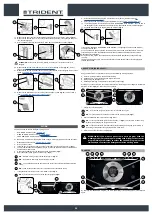
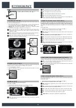
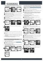
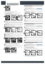
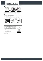
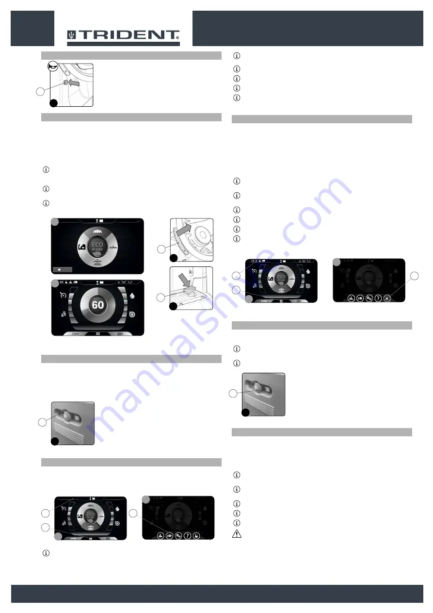
AUTOMATIC REQUEST FOR TECHNICAL ASSISTANCE (OPTIONAL) 24
The machine has an automatic service for activating an urgent technical assistance request. To activate
this function, the operator only has to press the button under the hatch (1) bearing the symbol “SOS”.
N.B.
: in order to activate this urgent technical assistance request the machine needs to be
equipped with the HILLYARD FLEET MANAGEMENT kit.
N.B.
: in order to send a technical assistance request the machine needs to be on and should be
in a zone with data traffic coverage.
1
1
AUTOMATIC DETERGENT DOSING SYSTEM (OPTIONAL)
Upon request, the machine can be fitted with a system that measures out the detergent separately from
the water in the solution tank.
To start it do as follows.
1. With the machine on, press the menu button (1) on the working screen (
Fig.1
).
2. Press the FSS system activation/deactivation button (2) (
Fig.2
).
N.B.
: if the symbol (2) is grey the FSS system is not active, if the symbol (2) is green the FSS
system is active.
N.B.
: to quit the menu screen, wait a short time without pressing anything, or else press on any
point of the display (except one of the displayed buttons).
N.B.
: the FSS system activates when the electric pump in the machine's water system starts.
N.B.
: if the FSS system is activated, the relative symbol (3) is displayed in the working screen.
N.B.
: if you want to deactivate the FSS system press button (2) again.
ATTENTION
: before starting any work, remember to start the FSS system.
24


