N.B.
: to return to the working screen press on any point of the screen, except the edges of the
display or else wait three seconds without touching anything.
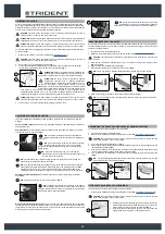
OFFICE
0000.00
100%
0000.00
100%
ECO mode
1
2
2
1
3
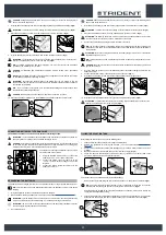
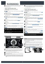
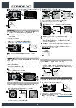
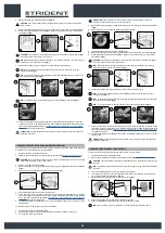
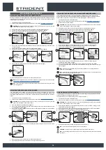
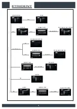
TUTORIAL
The machine's internal memory contains tutorials that explain:
• The initial commissioning of the machine (document in IT-EN-ES-FR-DE).
• The routine maintenance to be carried out (document in IT-EN-ES-FR-DE).
• The machine's use and maintenance manual (document in IT-EN-ES-FR-DE).
To start them do as follows.
1. With the machine on, press the menu button (1) on the working screen (
Fig.1
).
2. Press the TUTORIAL button (2) (
Fig.2
).
N.B.
: to return to the working screen press on any point of the screen, except the edges of the
display or else wait three seconds without touching anything.
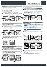
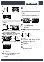
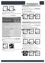
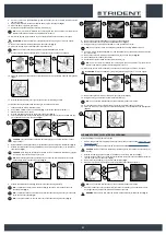
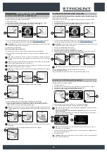
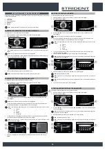
3. On the tutorial screen (
Fig.3
) select the topics you want to study:
A. Using the machine.
B. Daily maintenance.
C. Extraordinary maintenance.
N.B.
: select the “USING THE MACHINE” key (A) to view the video explaining the stages for
preparing the machine for work (
Fig.3
).
N.B.
: select the “DAILY MAINTENANCE” KEY (B) to view the video explaining the maintenance
to be carried out every day (
Fig.3
). When this button is selected the screen regarding the
selection of the videos to view will be displayed (
Fig.4
), you can view the following tutorial
videos:
• Draining and cleaning the recovery tank.
•
Cleaning the vacuum tube and the squeegee body.
•
Cleaning the vacuum motor filter.
•
Draining and cleaning the solution tank and the water system filter.
N.B.
: select the “EXTRAORDINARY MAINTENANCE” key (C) to see the video explaining the
maintenance to be carried out daily (
Fig.3
). When this button is selected the screen regarding
the selection of the videos to view will be displayed (
Fig.4
), you can view the following tutorial
videos:
•
Replacing the squeegee rubber blades.
• Replacing the brush head brushes.
•
Adjusting the squeegee rubber blades.
OFFICE
0000.00
100%
0000.00
100%
ECO mode
1
2
2
1
VIDEO TUTORIAL
Utilizzo della macchina
Manutenzione giornaliera
Interventi straordinari
Back
3
4
C
B
A
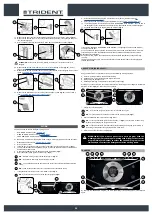
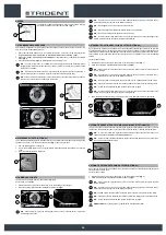
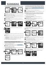
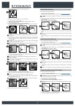
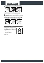
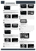
EMERGENCY BUTTON
If any serious problems are encountered during the work operations, press the emergency button (1)
on the electrical system's carter (
Fig.1
).
CAUTION
: This command interrupts the electrical circuit between the batteries and the machine
system.
N.B.
: After having stopped and resolved the problem, the work operations can be resumed by
doing the following:
• Set the main machine switch to “0” (
Fig.2
).
• Disengage the mushroom-head emergency button (1) (
Fig.3
).
• Set the main switch to "I" (
Fig.4
).
1
3
1
1
2
4
2
2
OFF
ON
REAR VIDEO CAMERA (OPTIONAL)
Upon request, the machine can be fitted with a rear video camera, which allows you to view the
condition of the floor where you have just passed over, and it also helps when reversing, allowing you
to identify any obstacles.
To activate the rear video camera, proceed as follows:
1. On any screen, press the “VIDEO CAMERA” button (1) (
Fig.1
).
2. As soon as the button (1) is pressed, the video camera image is shown full screen.
N.B.
: to exit the video camera screen, press on any point of the screen, except the edges of the
display.
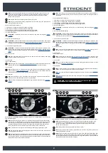
DRIVE
0000.00
100%
1
1
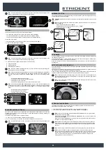
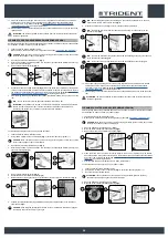
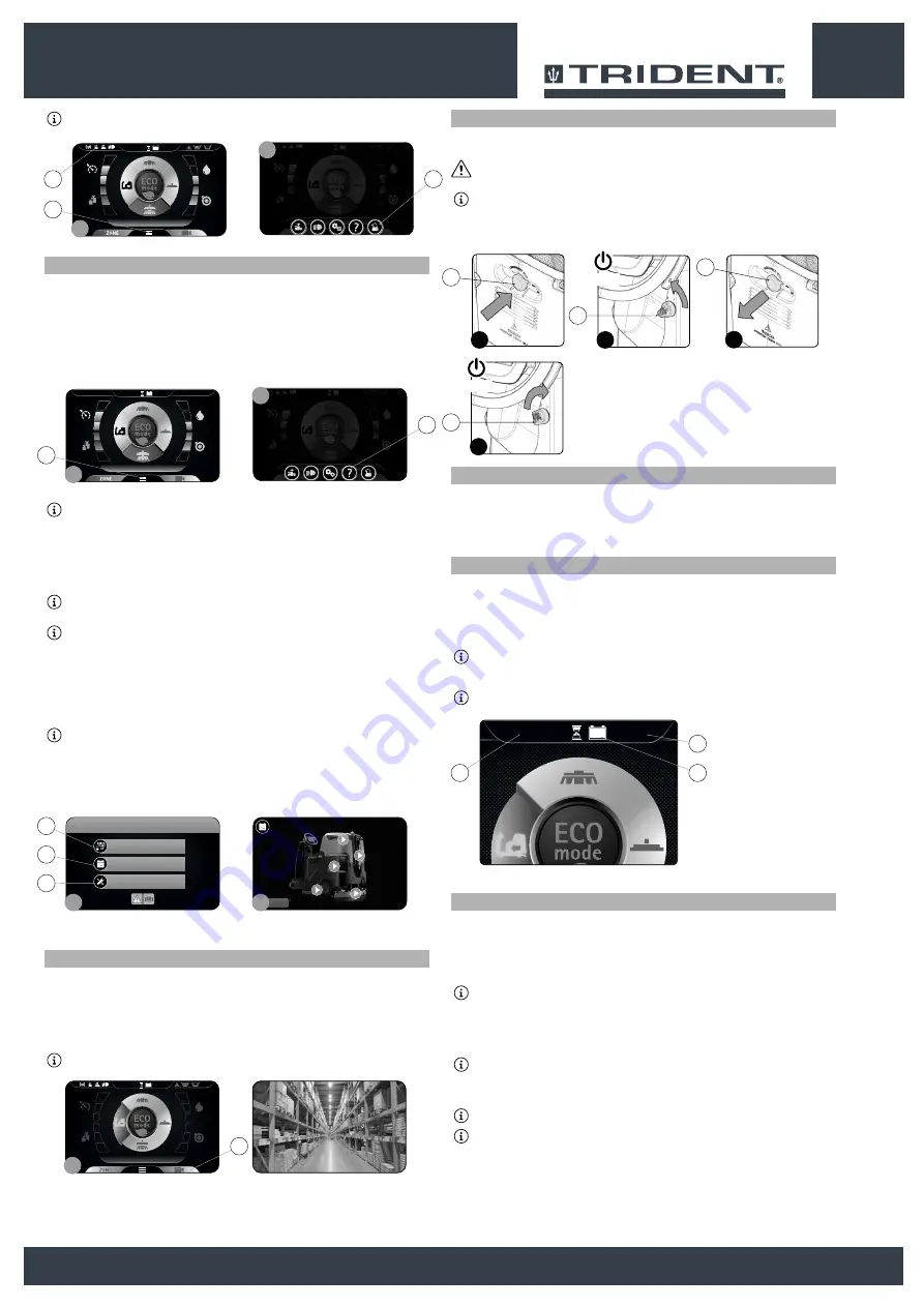
HOUR METER
The control display is in the control panel, at the top in the middle it is possible to observe the total time
the machine has been used.
The numbers before the "." symbol identify hours, while the number that follows it indicates hour
decimals (an hour decimal corresponds to six minutes).
When the “hour glass” symbol (1) is flashing it indicates that the hour meter is counting the appliance's
operating time.
BATTERY CHARGE LEVEL INDICATOR
The control display is in the control panel, at the top in the middle it is possible to observe the charge
level of the batteries.
The indicator is composed of two charge level symbols, the first represented by a graphic symbol (2),
the second by a number that indicated the charge percentage (3).
With a low charge level the graphic symbol (2) will start to flash and after a few seconds it will switch off,
in these conditions take the machine to the place where its batteries can be charged.
N.B.
: a few seconds after the battery charge reaches the critical level, the brush gear motors
switch off automatically. With the remaining charge it is possible to complete the drying process
before starting the recharge.
N.B.
: A few seconds after the battery charge reaches the discharge level, the vacuum motor
switches off automatically.
DRIVE
0000.00
100%
3
2
1
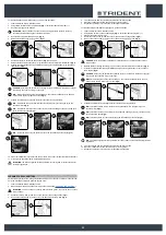
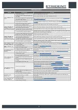
ACTIVATING THE SIDE BRUSH
If the lateral brush needs to be used during the floor scrubbing operations, and therefore with the
brush head in its working position, do as follows.
1. With the machine on, press the menu button (1) on the working screen (
Fig.1
).
2. press the ACTIVATION-DEACTIVATION OF LATERAL BRUSH 1SL (2) (
Fig.2
).
NB
: when the key
ACTIVATING-DEACTIVATING THE SIDE BRUSH 1SL (2)
is grey it shows
that the brush is not active
(
Fig.2
)
.
when the key
ACTIVATING-DEACTIVATING THE SIDE BRUSH 1SL (2)
is green it shows that
the brush is active
(
Fig.2
)
.
Moreover, when the
SIDE BRUSH 1SL
mode is active, the top left part of the screen displays
the symbol (3) specifically for this (
Fig.1
).
NB
: the lateral brush head starts to move towards the outside of the machine only when the
drive pedal (4) is pressed (
Fig.3
). Only when the lateral brush head is in the working position
will the solenoid valve begin to dispense the detergent solution (if the detergent level is other
than zero).
N.B.
: In order to bring the lateral brush head back to its resting position, press the button (2).
NB
: when the drive pedal is released all the brush head motors stop with the respective
delays. After the “Reset Delay”time all the brush heads are taken to the rest position (raised off
the floor). Even if the lateral brush head is in a rest position, the lateral brush function is still
active, in fact when the drive pedal (4) is operated all the brush heads are brought to the
working position (in contact with the floor).
25