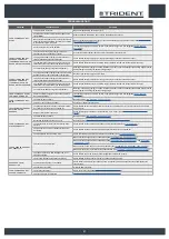
background image

TROUBLESHOOTING

This chapter lists the most common problems linked with the use of the machine. If you are unable to resolve the problems with the information given here, please contact your nearest assistance centre.
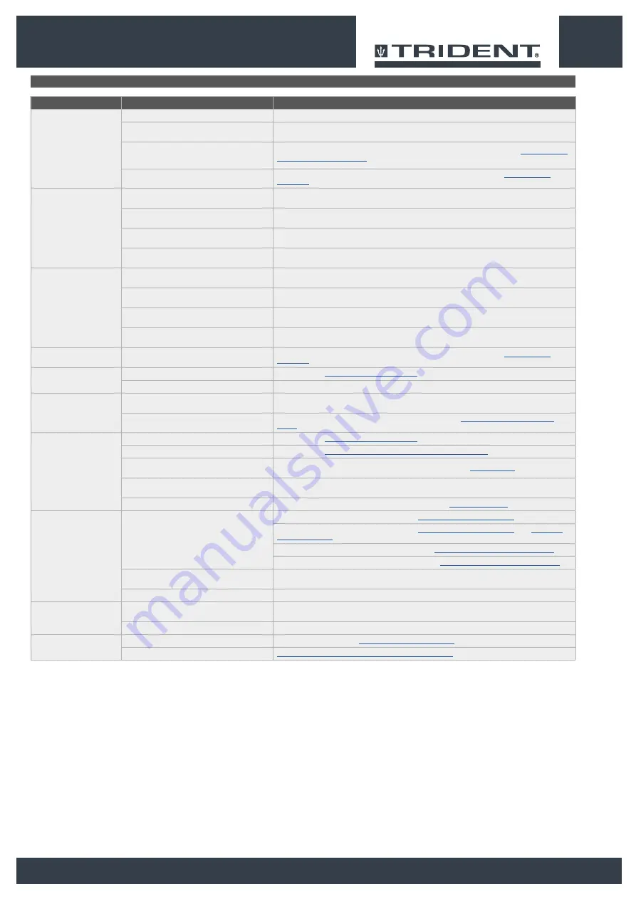
PROBLEM

POSSIBLE CAUSE

SOLUTION

THE MACHINE DOES NOT 

START

The main switch is set to “0”.

Make sure that the main switch is set to "I".

Check whether there are any alarm messages on the 

control display.

Stop the machine immediately, and contact a specialised service centre.

Make sure that the batteries are correctly connected to 

each other and that the battery connector is connected 

to the electrical system connector.

Make sure that the batteries are properly connected inside the machine (see the section titled 

INSERTING THE 

BATTERIES INTO THE MACHINE

”).

Check the charge level of the batteries.

If the battery charge level is critical, perform a complete recharge cycle (see paragraph 

CHARGING THE 

BATTERIES

”).

THE BATTERIES ARE NOT 

CHARGED CORRECTLY 

(VERSIONS WITHOUT AN ON 

BOARD BATTERY CHARGER)

The connector of the battery charger cable is not 

properly inserted in the battery connector.

Connect the battery charger cable connector to the battery connector again.

The plug on the battery charger's power cable is not 

correctly inserted into the electrical outlet.

Check that the battery charger power supply cable plug is connected to the mains socket.

The characteristics of the mains power supply do not 

correspond to those required by the battery charger.

Check that the characteristics in the battery charger plate are the same as those of the mains supply.

The LEDs of the battery charger blink repeatedly.

Referring to the battery charger use and maintenance manual, check the meaning of the flashing signals that the 

battery charger emits dung the battery recharge stage.

THE BATTERIES ARE NOT 

CHARGED CORRECTLY 

(VERSIONS WITH AN ON 

BOARD BATTERY CHARGER)

The plug on the battery charger's cable is not correctly 

inserted into the socket on the battery charger itself.

Reconnect the battery charger's power cable.

The plug on the battery charger's power cable is not 

correctly inserted into the electrical outlet.

Check that the battery charger power supply cable plug is connected to the mains socket.

The characteristics of the mains power supply do not 

correspond to those required by the battery charger.

Check that the characteristics in the battery charger plate are the same as those of the mains supply.

The LEDs of the battery charger blink repeatedly.

Referring to the battery charger use and maintenance manual, check the meaning of the flashing signals that the 

battery charger emits dung the battery recharge stage.

THE MACHINE HAS A VERY 

LOW WORK AUTONOMY

Check the battery charge level, check the symbol on 

the command display. 

If the battery charge level is critical, perform a complete recharge cycle (see paragraph 

CHARGING THE 

BATTERIES

”).

THE MACHINE DOES NOT 

MOVE

The machine does not start.

Read the section “

THE MACHINE DOES NOT START

”.

There is an issue on the drive pedal.

Contact your nearest service centre.

INSUFFICIENT DETERGENT 

SOLUTION ON THE 

BRUSHES

The quantity of detergent solution in the water system 

is not sufficient for the work to be carried out.

Check that the amount of detergent solution present in the machine's water system is sufficient for the work to 

be carried out.

Detergent solution filter obstructed.

Check the detergent solution filter isn't obstructed. If it is, clean it (see “

CLEANING THE WATER SYSTEM 

FILTER

”).

THE MACHINE DOES NOT 

CLEAN CORRECTLY

The machine does not start.

Read the section “

THE MACHINE DOES NOT START

”.

Not enough detergent solution comes out.

Read the section “

INSUFFICIENT DETERGENT SOLUTION ON THE BRUSHES

”.

The brushes have not been inserted correctly in the 

machine.

Check that the brushes have been inserted correctly (read the paragraph “

FITTING BRUSH

”).

The type of brush used is not suitable for the dirt to 

be cleaned.

Check that the brushes on the machine are adequate for the work to be carried out.

The brush bristles are excessively worn.

Check the condition of the brush, and replace it if necessary (see “

FITTING THE BRUSH

”).

THE SQUEEGEE DOES NOT 

DRY PERFECTLY

The vacuum unit is obstructed.

Make sure the squeegee is free of obstructions (read “

CLEANING THE SQUEEGEE BODY

”).

Make sure the squeegee is free of obstructions (read “

CLEANING THE SQUEEGEE BODY

” and “

CLEANING 

THE VACUUM TUBE

”).

Make sure the vacuum cap filter is free of obstructions (see “

CLEANING THE RECOVERY TANK FILTERS

”).

Make sure the vacuum motor filter is free of obstructions (see “

CLEANING THE RECOVERY TANK FILTERS

”).

The cap on the recovery tank drainage tube is not 

properly positioned.

Check that the cap on the recovery tank drainage tube is positioned properly.

The recovery tank lid is not positioned correctly.

Check that the recovery tank lid is properly positioned on the machine.

EXCESSIVE FOAM 

PRODUCTION

The detergent being used is not suitable.

Check that a low foam detergent has been used. If necessary, add a small quantity of anti-foam liquid to the 

recovery tank.

The floor is not very dirty.

Dilute the detergent more.

THE MACHINE DOES NOT 

VACUUM CORRECTLY

The recovery tank is full.

Empty the recovery tank (read “

EMPTYING THE RECOVERY TANK

”).

The vacuum device is obstructed

Read the section "THE SQUEEGEE DOES NOT DRY PERFECTLY

".

37

Summary of Contents for TRIDENT R36 SC 1SL PLUS

Page 1: ...Instructions originales DOC 10076229 Ver AA 06 2018 Scrubbing machine Use and Maintenance manual...

Page 2: ......

Page 3: ...e vacuum hose 16 Squeegee body 17 Command display 18 Brush head extra pressure selection lever 19 Horn button 20 Detergent solution tap control lever 21 Steering wheel 22 Reverse gear selection lever...

Page 4: ...CLING SYSTEM OPTIONAL 24 AUTOMATIC REQUEST FOR TECHNICAL ASSISTANCE OPTIONAL 24 AUTOMATIC DETERGENT DOSING SYSTEM OPTIONAL 24 TUTORIAL 25 REAR VIDEO CAMERA OPTIONAL 25 EMERGENCY BUTTON 25 HOUR METER 2...

Page 5: ...S DANGER If the battery charger power cable is damaged or broken it should be replaced by the manufacturer by authorised service personnel or else by a qualified person in order to protect against haz...

Page 6: ...ould not be done by unsupervised children In the event of danger take prompt action by pressing the emergency button near the operator s seat Never collect gases explosive inflammable liquids or powde...

Page 7: ...the machine only in the way described in this manual Do not pick up anything that is burning or smouldering like cigarettes matches or glowing embers Reduce speed on slopes and dangerous corners Redu...

Page 8: ...work check that all the safety devices have been installed and are working correctly Take all due precautions so that hair jewellery loose clothing do not get entangled in the machine s moving parts...

Page 9: ...ATTENTION Never tamper with the machine s protection devices for any reason always follow the supplied routine maintenance instructions scrupulously The electro magnetic brake must be released in ord...

Page 10: ...be carried out by qualified personnel Do not physically change the design characteristics of the machine Use spare parts supplied by HILLYARD or by HILLYARD service centres Wear personal protective e...

Page 11: ...onsible for machine operation The majority of occupational accidents that happen either in the workplace or whilst moving are caused by failure to respect the most basic safety rules An attentive care...

Page 12: ...ntral brush head rpm 180 180 Lateral brush head unit motor voltage nominal power rating V W 36 200 Lateral brush head brush rotations rpm 140 Side brushes number external bristles N in 1 11 4 Lateral...

Page 13: ...e nominal power rating V W 36 90 Lateral brush head brush rotations rpm 75 Side brushes number external bristles N in 2 17 7 Maximum weight exerted upon the central brush head lb 132 132 Maximum weigh...

Page 14: ...e indicates that the tank is full Main switch symbol Applied to the control panel positioned on the front of the machine to indicate the main switch Acoustic signalling device control label Applied in...

Page 15: ...Check that the main switch on the control panel has been set to 0 If this is not the case turn the key 2 a quarter turn anti clockwise Fig 2 Remove the key from the main switch 7 Grip the back of the...

Page 16: ...head and the squeegee support will be in the resting position raised from the floor N B in the DS selector the symbol of the transport program 1 is green Fig 1 N B the grey symbols show working progra...

Page 17: ...through contact with it ATTENTION the room used to recharge the batteries must be adequately ventilated to prevent the accumulation of gases that leak from batteries 3 Get off the machine CAUTION when...

Page 18: ...wer than the shoulders With a good grip on the steering wheel the elbows should be bent by about 120 They should be at least 30 cm between the middle of the steering wheel and our breastbone In any ca...

Page 19: ...1 Make sure the recovery tank is empty If this is not the case empty it read EMPTYING THE RECOVERY TANK 2 Check that the amount of detergent solution present in the solution tank is sufficient for th...

Page 20: ...ired work area and press the ZONE key see ZONE PROGRAM MODE 10 If a working program is selected which includes SCRUBBING WITH DRYING open the flow of the detergent solution into the machine s water sy...

Page 21: ...rush head motors stop with the respective delays After the Reset Delay time all the brush heads are taken to the rest position raised off the floor by pressing the forward movement pedal it will start...

Page 22: ...rs that were set before it stopped N B if you reverse with this program active the brush head will remain in contact with the floor the motor will continue working but the solenoid valve will not deli...

Page 23: ...essure exercised on the central brush head and performance level of the vacuum motor N B the disabled buttons and the respective indicators are grey N B each time one of the enabled keys is pressed it...

Page 24: ...ith a system that allows the detergent solution to be recycled so that productivity can be increased since the number of stops needed to empty and fill the tanks is reduced As a result less water and...

Page 25: ...ed as follows 1 On any screen press the VIDEO CAMERA button 1 Fig 1 2 As soon as the button 1 is pressed the video camera image is shown full screen N B to exit the video camera screen press on any po...

Page 26: ...nnect the vacuum tube 4 to the extension tube 3 Fig 4 2 3 Back 0000 00 100 1 1 5 Insert the vacuum brush 5 in the extension tube 3 Fig 5 6 Remove the vacuum tube 6 from the sleeve 7 in the squeegee bo...

Page 27: ...careful cleaning of the whole vacuum unit ensures better drying and cleaning of the floor as well as a longer vacuum motor life To carry out the cleaning of the squeegee body proceed as follows 1 Take...

Page 28: ...lace 8 Clean the brush under a stream of running water to remove any impurities from its bristles Check the wear status of the bristles and replace the brushes if they are excessively consumed the bri...

Page 29: ...8 Activate the optional tank cleaning kit ON OFF pump by pressing the button 6 on the back of the machine Fig 7 CAUTION when using the optional tank cleaning kit you are advised to always wear goggles...

Page 30: ...see the section titled SECURING THE MACHINE CAUTION these operations must be carried out using protective gloves to avoid any possible contact with the edges or tips of metal objects 3 Stand on the r...

Page 31: ...ssory itself Fig 8 N B to stop the solution jet use the lever 10 on the tank cleaning accessory Fig 9 5 6 7 6 8 4 5 7 DRIVE 0000 00 100 3 1 2 2 3 4 1 4 5 6 5 6 7 9 Remove the dirty water basket filter...

Page 32: ...ure the machine has been secured see the section titled SECURING THE MACHINE CAUTION users are advised to always wear protective gloves to avoid the risk of serious injury to hands 3 Close the tap s o...

Page 33: ...tled SECURING THE MACHINE ATTENTION users are advised to always wear protective gloves to avoid the risk of serious injury to hands 3 Extract the vacuum tube 1 from the vacuum nozzle on the squeegee b...

Page 34: ...OIL BASIN If a braking system anomaly alarm is activated when you are working quickly stop the machine and check the oil level in the machine s brake system To check and top up the oil in the braking...

Page 35: ...ot do their work properly namely convey the dirty detergent solution towards the squeegee therefore the height of the splashguard needs to be adjusted This operation can be done with the brush head bo...

Page 36: ...ing insert the retainer 8 into the slot 9 Fig 8 10 Disconnect the battery connector from the machine s main system connector Fig 9 11 Grip the back of the seat 7 and turn the seat support plate to the...

Page 37: ...l check the meaning of the flashing signals that the battery charger emits dung the battery recharge stage THE MACHINE HAS A VERY LOW WORK AUTONOMY Check the battery charge level check the symbol on t...

Page 38: ...4 Esci ZONE MANUAL ON OFF Programmazione Zone Zone 1 Zone 2 Zone 3 Zone 4 Esci ZONE MANUAL ON Monitor General Brush Pump Vacuum Traction Esci Valore 1 100 Valore 2 23 5 Valore 3 Valore 4 A V OFF ON P...

Page 39: ...Programmazione Zone Parametri Monitor Allarmi Esci VISUALIZZATO TOTALE PARZIALE Chiave 0000 00 0000 00 Trazione 0000 00 0000 00 Spazzole 0000 00 0000 00 Aspirazione 0000 00 0000 00 Chiave 3 4 3 5 4 R...

Page 40: ...ress the menu button 1 on the working screen Fig 1 2 Press the setting 2 Fig 2 3 In the MAIN MENU screen select the ZONE PROGRAMMING option 3 on the left hand side of the screen Fig 3 N B when the but...

Page 41: ...EXIT key Reset Menu principale Lingua Contaore Programmazione Zone Parametri Monitor Allarmi Esci VISUALIZZATO TOTALE PARZIALE Chiave 0000 00 0000 00 Trazione 0000 00 0000 00 Spazzole 0000 00 0000 00...

Page 42: ...immediate stopping of the entire machine or a part of it ALARM NUMBER DESCRIPTION AL_12 General Update in progress AL_15 General Brake fluid reserve AL_46 Function Overcurrent Outputs Brushes 1 2 3 A...

Page 43: ......

Page 44: ...HILLYARD INDUSTRIES PO Box 909 St Joseph Missouri 64502 0909 U S A Telephone 816 233 1321 www hillyard com...

Reviews: