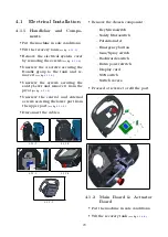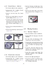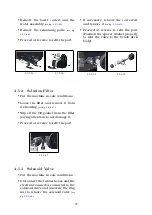
• Remove the electrical system cover
by removing the screws
(see fig.
.
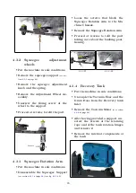
• Disconnect all the cables, remove
the 4 screws securing the board to
the panel and remove it
(see fig.
.
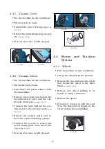
• Disconnect the Actuator Board from
the connector of the Main Board
(see
fig.
.
4.1.2-6
4.1.2-7
4.1.2-8
4.1.2-9
4.1.3
Battery Charger
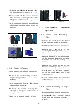
• Put the machine in safe conditions.
• Remove the rear Carter by unscrew-
ing the fixing screws
(see section
at page
.
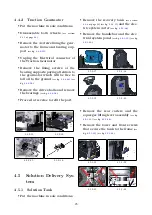
• Disconnect the charger cables from
the machine harness.
• Remove the screws securing the
charger to the panel and remove it
(see fig.
.
• Proceed at reverse to refit the part.
4.1.3-10
4.1.3-11
4.2
Mechanical
Friction
System
4.2.1
Brush Deck Assembly -
Disc
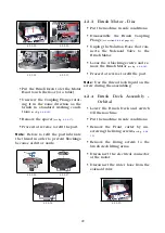
• Release the brush, lower the Brush
Deck and switch Off the machine.
• Put the machine in safe conditions.
• Remove the Front carter by un-
screwing the fixing screws
(see fig.
• Remove the Knob for the Adjustment
of the Machine Direction, together
with the rod and the spring
(see fig.
.
• Remove the fixing screws to the
brush deck lifting arms
(see fig.
.
• Disconnect the electrical connec-
tor of the brush motor and of the
solenoid valve.
• Disconnect the water hose from the
solenoid valve.
(see fig.
4.2.2
Brush Coupling Flange -
Disc
• Put the machine in safe conditions.
• Disassemble the complete Brush
Deck from the machine
(see section
at page
.
21
Summary of Contents for TRIDENT T20SC PRO
Page 1: ...SERVICE MANUAL TRIDENT T20SC PRO Version AB Date November 7 2018 Document Number 10077483...
Page 4: ...Part I Product Introduction 4...
Page 8: ...Part II Anomalies Resolution Guide 8...
Page 28: ...Part III Machine Description 28...

