background image

5.7

Menu Tables

5.7.1

Menu Tree

• Make sure the machine is turned off.

• Press simultaneously the buttons 3,4,6.

• Turn on the machine while holding down the buttons.

• Wait the loading of the Operator Menu.

• For the submenus of the Advanced Menu, refer to the specific tables.

42

Summary of Contents for TRIDENT T20SC PRO

Page 1: ...SERVICE MANUAL TRIDENT T20SC PRO Version AB Date November 7 2018 Document Number 10077483...

Page 2: ...to do if 12 3 4 Frame and traction system what to do if 14 3 5 Solution delivery system what to do if 15 3 6 Alarm Table 16 4 Disassembling Procedures 18 4 1 Electrical Installation 19 4 2 Mechanical...

Page 3: ...Adjustments 53 7 4 Maintenance and Checks 53 8 Machine Frame and Traction System 56 8 1 Structure 56 8 2 Description 56 8 3 Maintenance and Checks 57 9 Cleaning Solution Supply System 58 9 1 Structur...

Page 4: ...Part I Product Introduction 4...

Page 5: ...s necessary to lift the recovery tank The Serial Number is an extremely important information which has to be provided each time a Technical Support is required or is necessary to buy spare parts or a...

Page 6: ...Nominal Power V W 24 420 Vacuum motor Stages Nr 2 Vacuum group suction mbar 91 4 Steering diameter in 77 Suggested battery Voltage Power V AhC5 12 110 Maximum batteries weight lb 180 Battery compartm...

Page 7: ...Width with squeegee in 28 28 Weights and Pressures T20SC PRO2 TECHNICAL DESCRIPTION U M Disc Orbital Machine Weight empty and without batteries lb 152 167 Machine Gross Weight work condition machine b...

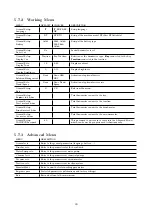
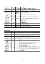
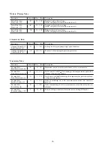
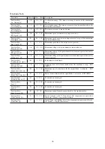
Page 8: ...Part II Anomalies Resolution Guide 8...

Page 9: ...n 1 The key is in position 0 Rotate the key in position I 2 The key microswitch is not properly connected Restore the proper connections 3 The key microswitch doesn t work Replace the key microswitch...

Page 10: ...s are damaged Replace the damaged wires 7 The battery charger is not properly adjusted Adjust properly the battery charger see section 5 4 1 at page 35 8 The battery charger doesn t work Check the pro...

Page 11: ...grease 2 When the machine is working a bat tery voltage is lower and lower than the other batteries The difference is bigger than 2V Replace the battery with the lower voltage 3 The battery charger is...

Page 12: ...doesn t work Replace the safety switch see section 4 1 1 at page 19 6 The brush deck motor is not sup plied Verify the motor connections 7 The carbon brushes are worn out Replace the carbon brushes se...

Page 13: ...t properly ad justed Adjust the squeegee properly follow ing the proper procedure see section 7 3 1 at page 53 9 The squeegee vacuum chamber or adapter is stuck or dirty Clean the squeegee vacuum cham...

Page 14: ...s sage Check what alarm message is shown and solve the related issue by following the proper instructions see section 3 6 at page 16 4 The vacuum motor carbon brushes are worn out Replace the vacuum m...

Page 15: ...sengage Check the electro brake connections 5 The safety lever is not pressed Push the safety lever 6 The safety microswitch is not prop erly connected Restore the proper connection to the safety micr...

Page 16: ...Open the water valve to the desired position 5 The water flow is adjusted at mini mum Increase the water flow adjustment 6 The solenoid valve doesn t work Check the solenoid valve connec tions and if...

Page 17: ...e scrub deck position AL 8 Function Actuator Stroke End Position not reached Check the connections of the actuator AL 9 Function Squeegee actuator Stroke end position not reached Check the connections...

Page 18: ...the connection are OK the general relay on the main card is damaged replace the main card The same alarm is present also if power fuse is damaged AL 23 General Overvoltage Overvoltage Detected a overv...

Page 19: ...PERATION DESCRIBED BELOW VERIFY THAT THE MACHINE TANKS ARE COMPLETELY EMPTY THE MACHINE HAS TO BE TURNED OFF DISCONNECT THE BATTERIES AND REMOVE THEM FROM THE MACHINE AT LAST VERIFY THAT THE PARKING B...

Page 20: ...er and remove it from the pivot see fig 4 1 1 4 Unscrew the central and external screws securing the lower part from the upper part see fig 4 1 1 5 Disconnect the cables 4 1 1 1 4 1 1 2 4 1 1 3 4 1 1...

Page 21: ...1 Proceed at reverse to refit the part 4 1 3 10 4 1 3 11 4 2 Mechanical Friction System 4 2 1 Brush Deck Assembly Disc Release the brush lower the Brush Deck and switch Off the machine Put the machine...

Page 22: ...tions Disassemble the Brush Coupling Flange see section 4 2 2 at page 20 Unplug the Solution Hose that con nects the Solenoid Valve to the Brush Motor Loose the 4 blocking screws and re move the Brush...

Page 23: ...the machine see section 4 2 1 at page 20 see section 4 2 4 at page 21 Release the plug and disconnect the actuator arm from the brush deck arm Remove the elastic ring and remove the actuator from its...

Page 24: ...see section 4 3 1 at page 22 see fig 4 3 3 25 Loose the screws that block the Squeegee Rotation Arm to the Ma chine Chassis Remove the Squeegee Rotation Arm Proceed at reverse to refit the part taking...

Page 25: ...nuts that fix the suc tion motor to the recovery tank see fig 4 3 6 30 Remove the suction motor and re move the sound absorbing sponge Unscrew the screws to remove the motor fixing plate and remove th...

Page 26: ...earings see fig 4 4 2 36 Proceed at reverse to refit the part 4 4 2 33 4 4 2 34 4 4 2 35 4 4 2 36 4 5 Solution Delivery Sys tem 4 5 1 Solution Tank Put the machine in safe conditions Remove the recove...

Page 27: ...om the filter paying attention to not damage it Proceed at reverse to refit the part 4 5 2 47 4 5 3 Solenoid Valve Put the machine in safe conditions Disconnect the rubber hoses and the electrical con...

Page 28: ...Part III Machine Description 28...

Page 29: ...ion from the control board the safety microswitch and all the electronic devices of the machine These signals are translated from the main board to run correctly the scrubber dryer and to prevent any...

Page 30: ...5 3 Location of Electrical components 30...

Page 31: ...owitch 10 Solenoid Valve 11 Electro brake 12 Potentiometer 13 Gun Wand activation switch 14 Recycle Dosing system Switch 15 Forward Backward switch 16 Brush extra pressure switch 17 Display hourmeter...

Page 32: ...he input informa tion decides how to use the devices of the machine during normal work On the table here below is possible to identify the input output signals of the board Board Cables Legend Power C...

Page 33: ...d Positive 14 B Green Positive 15 B 21 Pink Positive 16 Key In 15 Gray Positive J2 1 Dashboard Communication 20 Blue Reception 2 Dashboard Communication 20 Brown Transmission 3 Dashboard Communication...

Page 34: ...o modify the ad vanced settings and thanks to the Monitor Mode function check the motors absorption ATTENTION THE OPERATOR MENU IS ACCESSIBLE WITHOUT ANY RESTRICTION WHEREAS TO ENTER INTO THE ADVANCED...

Page 35: ...irectly connected to the same handle This microswitch runs the brush base and the traction of the machine 5 3 5 3 5 3 6 Potentiometer The adjustment knob of the potentiome ter located on the control p...

Page 36: ...of battery status B Red First charging phase C Yellow Second charging phase D Green Charged battery Check if the charger is properly set according to the installed batteries Charging curve SetUp To s...

Page 37: ...rough successive flashes of the yellow LED Error code Flash Description 1 Battery not connected or reverse polarity or output short circuit Verify the battery connection 2 Alarm time out damaged batte...

Page 38: ...the amperometric values be cause it can change depending of the working conditions 5 5 Maintenance and Checks 5 5 1 Electrical System Check to perform every 150h Check the functions and the proper co...

Page 39: ...OLL UP Increase the Value 4 SCROLL DOWN Decrease the Value 5 ENTER Confirm Exit 5 6 2 How to access the Opera tor Menu To enter to the Operator menu go ahead as follow With the machine off press in th...

Page 40: ...he action with the button 5 to return to the Work Menu 5 6 4 For example to modify the language from GEL60 to Pb60 Turn OFF the machine With the machine off press at the same time button 1 2 While the...

Page 41: ...he but tons 1 2 until you find exit Confirm the new value by pressing the button 5 to return to the Work Menu 5 6 6 Use of the Monitor Mode Function The Check Monitor function allows to check The batt...

Page 42: ...ake sure the machine is turned off Press simultaneously the buttons 3 4 6 Turn on the machine while holding down the buttons Wait the loading of the Operator Menu For the submenus of the Advanced Menu...

Page 43: ...u General Setup Key on ctn h m Total hourmeter connect to the key General Setup Tract motor h m Total hourmeter connect to the traction General Setup Brush motor h m Total hourmeter connect to the bru...

Page 44: ...ent A 40 20 50 Maximum current from the main board to the brush motor Brushes Sets Nom Mot current A 25 10 40 Rated current with T Nom manages the amperometric protection alarm stop brush motor Brushe...

Page 45: ...Sets 2 0 0 5 3 0 Position 1 of the detergent percentage selector Vacuum Sets Parameter Default Min Max Description Vacuum Sets Max Mot current A 40 10 40 Maximum current from the main board to the vac...

Page 46: ...s pressed Traction Sets BW pos ref V 4 8 0 5 13 0 Maximum voltage of the potentiometer in backward speed when safety lever is pressed Traction Sets Deadband ref mV 20 0 50 Potentiometer dead band Trac...

Page 47: ...ow current of traction motor Monitor Sets Tract Ammeter Maximum overload of traction motor Monitor Sets Brushes Current A Show current of brush motor Monitor Sets Vacuum Current A Show current of vacu...

Page 48: ...rt present on the floor To facilitate and enhance this interac tion is used a system of mechanical rub bing which consists in a device which rubs on the floor This device can be of various nature pad...

Page 49: ...ft connected to the flange provides the rotational movement Figure 6 2 T20SC ORBITAL PRO 6 1 3 Structure T20SC OR BITAL PRO Motor Brush Deck and Support Eccentric Flange brush deck Plate Brass bushing...

Page 50: ...fig 6 2 1 1 Place on the front of the brush be tween the brush and the floor a spacer of about 1 5 inch thick see fig 6 2 1 2 Lower the brush deck to the ground and tighten the fixing screw of the lef...

Page 51: ...0 6 brushes and activate the brush motor the current absorption must be less than 25 Ampere in stan dard mode and less than 37 Ampere in Power mode The motor should rotate evenly and smoothly and does...

Page 52: ...he base is locked in a position without the possibility of move ment is important that the brass bush ings are in good condition and clean In case of excessive wear it is necessary to proceed with the...

Page 53: ...m which vacuum it out from the floor The system is basically made by a vac uum motor which produces an under pressure in the system This underpres sure causes an air flow which flows in the whole vacu...

Page 54: ...7 3 1 1 see fig 7 3 1 2 When the operation is performed verify that height and inclination adjustment bubble levels of the squeegee are in central position see fig 7 3 1 3 Check functionally the resu...

Page 55: ...he squeegee support eyelet 7 4 2 8 7 4 2 9 At the end of the assemblying per form the proper squeegee adjust ment see section 7 3 1 at page 53 7 4 3 Vacuum Hose Check to perform every 4h The vacuum ho...

Page 56: ...ely empty Rotate the Recovery tank lid Unscrew and remove the filter pro tection and the filter Verify that the filter ball is free to move and intact Remove and clean replace if neces sary the filter...

Page 57: ...n system and the tanks group The machine traction is given by the electric motor installed with a reduction gear whose output shafts act directly on the machine front wheels ensuring trac tion All mod...

Page 58: ...e complete in every part and show no signs of cracks The cables must be flexible When lifting the ma chine to put the front wheels in neutral by spinning a wheel in any sense the other must turn in th...

Page 59: ...filter is used to stop debris that could stuck the hose system and compromise the proper functioning of the system the water valve is used to adjust the solution that will fall on the floor in order...

Page 60: ...hoses 9 3 3 Water Valve Check to perform every 50h It is extremely important that when ad justed at minimum the valve blocks completely the water flow and it is me chanically free to move for its whil...

Page 61: ...Blue 405631 BRUSH PPL 0 6 20 PPL 0 023 White 404653 BRUSH PPL 0 9 20 PPL 0 035 Black 405632 BRUSH TYNEX 20 ABRASIVE 0 035 Gray 405527 PAD HOLDER 20 Carbon Brushes 422462 BRUSH MOTOR CAR BR T20SC ORBIT...

Page 62: ...RUBBER KIT PARA 40Sh 31 x 2 5 x 0 25 in 227174 RUBBER KIT POLY 40Sh 31 x 2 5 x 0 25 in 227175 RUBBER KIT Linatex 30Sh 31 x 2 5 x 0 25 in 438487 SQUEEGEE WHEEL D 3 L 1 10 1 3 Machine Frame and Tractio...

Page 63: ...22 C ROTEL 446355 POTENTIOMETER 409499 SQUEEGEE MICROSWITCH 3X22 L C 446650 MAIN BOARD 7CFS1030 442888 ACTUATOR BOARD 7MDAC030 446672 DISPLAY BOARD 7T100000 446359 HANDLE BUTTON BOARD 7CFCT020 10 2 2...

Page 64: ...E FILTER ASSEMBLY D 60 H 130 436190 GAS SPRING L 146 150N 445710 DRAIN HOSE D 38x1100 D 50 CAP 445709 VACUUM HOSE D 38 L 1450 10 2 4 Machine Frame and Traction System PN Description 224910 TRACTION MO...

Page 65: ...Hillyard Inc Service Manual TRIDENT T20SC PRO Hillyard Inc 302 North 4th Street P O Box 909 St Joseph Missouri 64501 USA Tel 1 800 365 1555 Fax 1 800 881 3840 Edition November 7 2018...

Reviews: