background image

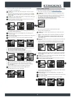
SYMBOLS USED ON THE MACHINE

LABELS USED ON THE MACHINE

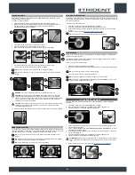
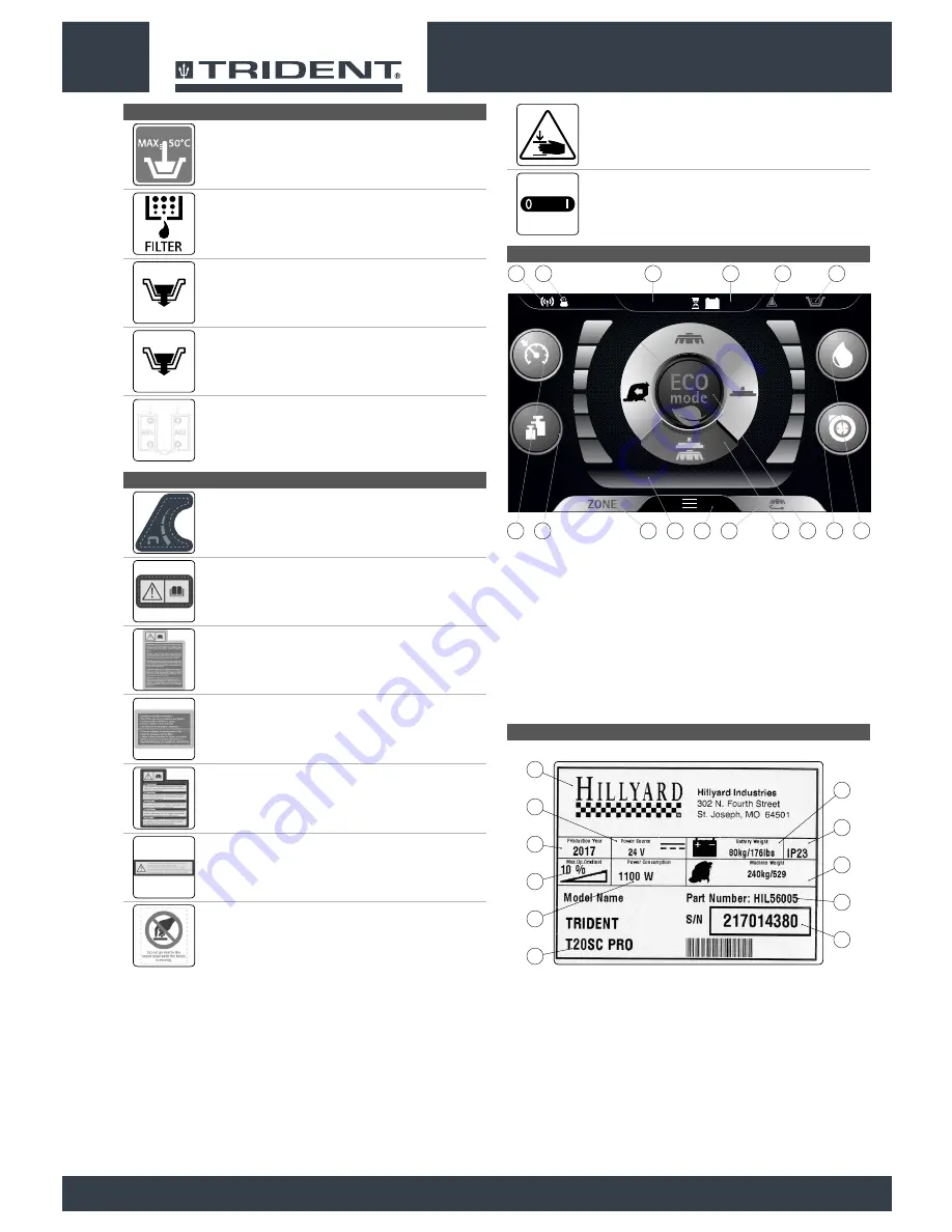
SYMBOLS ON THE CONTROL DISPLAY

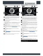
Symbol of maximum temperature for filling the solution tank:

Located on the front of the solution tank, to indicate the maximum temperature 

of the water for filling the solution tank safely.

Filter body position symbol:

Located on the right-hand side of the machine to indicate the position of the 

detergent solution filter.

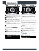
Label for detergent solution tap control:

Located on the right-hand side of the machine, to identify the control knob of 

the detergent solution tap.

Label indicating the need to read the Use and Maintenance Manual:

Attached to the machine in order to warn the operator to read the user and 

maintenance manual (this document) before using the machine for the first 

time.

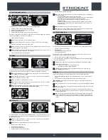
Battery recharge warning label:

Located inside the machine (above the electric system carter), to warn the 

operator when it's necessary to recharge the batteries.

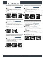
Daily care warning label:

Applied to the machine to remind the operator of the necessary procedures to 

properly care for the machine itself.

Machine use warning label:

Located on the rear of the machine, to warn the operator which substances 

cannot be removed with the machine.

Solution tank filter daily care warning label:

Applied to the machine to remind the operator to clean the solution tank after 

each use.

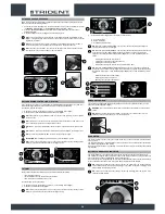
Moving brush hazard label:

Used on the machine to warn the operator not to place his/her hands near the 

moving brush.

Label warning about the risk of crushed hands:

Indicates danger to hands due to crushing between two surfaces.

Position symbol for the solution tank drainage cap:

Applied to the back of the machine to identify the solution tank drainage cap.

Position symbol for the recovery tank drainage tube:

Applied to the back of the machine to identify the recovery tank drainage tube.

Battery connection symbol:

Located on the front of the solution tank, to indicate how to connect the 12V 

batteries in order to obtain a total voltage of 24V.

Main switch symbol:

Located near the control panel, to indicate the main key switch.

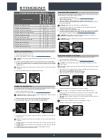
The serial number plate shows the following information:

1.  The weight of the batteries that power the machine (expressed in kg).

2.  The IP protection rating of the machine.

3.  The gross weight of the machine (expressed in kg).

4.  The machine ID code.

5.  The machine serial number.

6.  The machine ID name.

7.  The nominal power consumed by the machine (expressed in W).

8.  The maximum grade that the appliance can handle during work activities (expressed as %).

9.  The year of machine manufacture.

10.  The nominal voltage of the machine (expressed in V).

11.  The commercial name of the machine, and the manufacturer's address.

SYMBOLS USED ON THE SERIAL NUMBER PLATE

1.  HFM symbol, if visible it shows that the “HILLYARD FLEET MANAGEMENT” system is active.

2.  HDC symbol, if visible it shows that the “HILLYARD DOSING CONTROL” system is active.

3.  Hour meter.

4.  Battery charge level percentage.

5.  General alarm symbol.

6. 

Solution tank float symbol. If visible, it shows that the recovery tank is empty and that to continue 

you need to fill it.

7.  Detergent solution level symbol.

8.  Vacuum motor performance level symbol.

9.  HILLYARD ECO MODE program button.

10.  Drive Select selector.

11.  Brush uncoupling button (single-brush version).

12.  Menu screen activation button.

13.  Text indicator.

14.  Zone program selector button.

15.  Brush head extra pressure level symbol.

16.  Forward speed level symbol.

12

1

10

11

2

9

3

8

4

7

5

6

MANUAL

0000.00

100%

1

2

3

4

5

14

16

13

15

6

7

9

8

10

12

11

Summary of Contents for TRIDENT T26 SC PLUS

Page 1: ...Scrubbing machine Use and maintenance manual Translation of the original instructions DOC 10075757 Ver AA 11 2017 ...

Page 2: ......

Page 3: ...in battery charger 17 Solution tank drainage cap 18 Squeegee body 19 Squeegee body support 20 Squeegee vacuum tube 21 Water flow adjustment tap 22 Vacuum accessory support 23 Brush support 24 Squeegee body support 25 Headlights 26 Brush head body 27 Solution tank 28 Solution tank filler cap measuring inlet 29 Solution tank filler tube cap 30 Cover cap for HFF HILLYARD FAST FILL quick coupling kit ...

Page 4: ...ING THE SQUEEGEE BODY 15 FILLING THE SOLUTION TANK WITH WATER 15 DETERGENT SOLUTION VERSIONS WITHOUT HDC 15 FILLING THE DETERGENT CANISTER VERSIONS WITH HDC 15 PREPARING TO WORK 16 WORK 16 TRANSFER 17 SCRUBBING WITHOUT DRYING 17 DRYING 18 SCRUBBING WITH DRYING 18 DS SELECTOR DRIVE SELECT 19 ECO MODE 19 MANUAL MODE 19 ZONE PROGRAM BUTTON 19 REVERSE 19 EXTRA BRUSH HEAD PRESSURE 20 HILLYARD DOSING CO...

Page 5: ...es Explosive gases are emitted during normal use Highly explosive hydrogen gas is generated while charging the batteries Keep the recovery tank unit in the maintenance position during the entire battery recharging cycle and only perform the procedure in well ventilated areas at a safe distance from any open flames Before charging make sure the electric cable that connects the battery charger to th...

Page 6: ...unsupervised children The machine must only be used by authorised trained personnel Do not use the machine on surfaces with a slope greater than the one indicated on the serial number plate The machine is not suitable for cleaning rough or uneven floors Do not use the machine on slopes In the event of a fire use a powder extinguisher Do not use water Adapt the speed to the adhesion conditions Do n...

Page 7: ...heights Do not place any liquid containers on the machine The machine must only be used in temperature conditions ranging from 32 F to 104 F When using detergents to clean the flooring always follow the instructions and respect the warnings indicated on the container labels Always use appropriate gloves and protective equipment when handling the detergents used to clean the floor Avoid working wit...

Page 8: ... allow metallic objects to fall on the electrically powered components remove rings watches and or clothing with metallic parts that might come into contact with the electrically powered components Do not work underneath the raised machine without adequate fixed safety supports WARNING Read all the relevant instructions carefully before performing any maintenance repair operations If the machine d...

Page 9: ...es of the site regarding battery removal If the machine needs to be tilted for maintenance procedures remove the batteries Have the machine checked by an authorised technical assistance centre every year When disposing of consumable materials observe the laws and regulations in force Once the machine has reached the end of its service life the materials contained within it must be disposed of in a...

Page 10: ...ntenance Manual must be stored in its special pouch close to the machine protected from liquids and anything else that could compromise its legibility ON CONSIGNMENT OF THE MACHINE When the machine is consigned to the customer an immediate check must be performed to ensure all the material mentioned in the shipping documents has been received and also to check the machine has not suffered damage d...

Page 11: ...ement weight 2 10 Maximum slope during ascent and descent with the transport program weight 2 10 Maximum ambient temperature for machine operation F 104 Minimum ambient temperature for using the machine s scrubbing functions F 32 Traction motor voltage rated power V W 24 180 Traction wheel external Ø width in 8 9 x 2 6 Maximum forward speed in transport mode mph 3 TECHNICAL DATA US cu TRIDENT RS26...

Page 12: ...the machine to identify the solution tank drainage cap Position symbol for the recovery tank drainage tube Applied to the back of the machine to identify the recovery tank drainage tube Battery connection symbol Located on the front of the solution tank to indicate how to connect the 12V batteries in order to obtain a total voltage of 24V Main switch symbol Located near the control panel to indica...

Page 13: ...the handle 2 and raise the recovery tank to the maintenance position Fig 3 19 Disconnect the backup battery carriage connector from the main machine system connector Fig 4 20 Grip the handle 4 and lower the recovery tank to its working position Fig 5 HOW TO MOVE THE MACHINE To transport the machine safely proceed as follows DANGER before starting any task make sure the current regulations concerni...

Page 14: ...ic weight and size WARNING the lifting hooks must not damage the blocks connectors or cables WARNING before inserting the batteries remember to cover the terminals with a little grease to protect them against external corrosion The various phases for inserting the batteries in the battery compartment are as follows 1 Using the supplied jumper cable 1 connect the batteries to the and poles in seque...

Page 15: ...in a safe condition see MACHINE SAFETY MEASURES 3 Check the solution tank drainage cap 1 on the rear right hand side of the machine is tight If it isn t turn it clockwise Fig 1 4 Check the water filter cap 2 on the rear right hand side of the machine is tight If it isn t turn it clockwise Fig 2 The solution tank can be filled with water in three different ways Removing the cap measuring device 3 F...

Page 16: ... Make sure the vacuum motor filter 12 is correctly connected and is clean Fig 11 If it isn t clean it see CLEANING THE RECOVERY TANK FILTERS 16 Make sure the filter basin 13 is correctly connected and is clean Fig 12 If it isn t clean it see CLEANING THE RECOVERY TANK FILTERS 17 Make sure the recovery tank cover is properly closed If it isn t close it WORK To start working proceed as follows 1 Mak...

Page 17: ...r The brush head solenoid valve and the water system pump are powered up only if the detergent solution is other than zero When the dead man s lever is pressed the brush head solenoid valve electric pump and traction motor are powered NB on the DS selector the symbol of the scrubbing without drying program B is green NB the grey symbols show working programs that are not active the green symbols s...

Page 18: ...NG Selecting the program SCRUBBING WITH DRYING the control display screen will appear as shown in the figure NB with this working program the pressing of the dead man s lever brings both the brush head and the squeegee to the work position in contact with the floor When the dead man s lever is pressed all the motors are powered The brush head solenoid valve and the water system pump are powered up...

Page 19: ... will be those of maximum speed detergent solution adjustment and pressure exerted on the central brush head Drying the buttons visible will be those of maximum speed and vacuum motor performance level Scrubbing with Drying the buttons visible will be those of maximum speed detergent solution adjustment pressure exerted on the central brush head and vacuum motor performance level NB the disabled b...

Page 20: ...the machine B Daily maintenance C Extraordinary maintenance NB select the USING THE MACHINE key A to see the video explaining the stages for preparing the machine for work Fig 3 NB select the DAILY MAINTENANCE key B to see the video explaining the maintenance to be carried out every day Fig 3 When this button is selected the screen regarding the selection of the videos to view will be displayed Fi...

Page 21: ...and a brief description When an error occurs proceed as follows 1 Stop the machine and press the button 2 Fig 2 2 If the error persists switch off the machine and wait at least ten seconds before switching it back on NB to close the error screen press the button 3 Fig 2 3 If the error persists contact your nearest service centre NB the symbol 1 Fig 1 remains visible until the error has been resolv...

Page 22: ... 3 in the direction shown in the image Fig 2 ATTENTION Fig 2 shows the rotation direction of the left hand brush 6 When brush rotation is prevented turn until the button on the brush is disengaged from the coupling spring on the brush holder plate 7 Repeat the same operation for the right hand brush 8 Clean the brush under running water to remove any impurities from its bristles Check the bristles...

Page 23: ...proceed as follows 1 Make sure the machine is in a safe condition see MACHINE SAFETY MEASURES CAUTION users are advised to always wear protective gloves to avoid the risk of serious injury to hands 2 With the recovery tank empty grip the handle 1 on the left hand side of the tank Fig 1 and turn the tank cover as far as it will go until it reaches the maintenance position 3 Rinse the inside of the ...

Page 24: ...erse order to reassemble all the parts CLEANING THE SOLUTION TANK Proceed as follows to empty the solution tank 1 Take the machine to the maintenance area 2 Make sure the machine is in a safe condition see MACHINE SAFETY MEASURES CAUTION users are advised to always wear protective gloves to avoid the risk of serious injury to hands 1 Fully open the tap outflow rotating the knob 1 in the direction ...

Page 25: ...dy 4 Loosen the retainer knob 3 of the squeegee tilt adjustment knob 4 Fig 3 5 To adjust the tilt of the squeegee body rubber blades in relation to the floor tighten or loosen the knob 5 Fig 4 until the blades are bent outwards by about 30 in relation to the floor in an even manner along their entire length NB make sure the adjustment is correct by looking at the instrument 6 on the squeegee body ...

Page 26: ...S NOT START There is a drive pedal fault Contact your nearest service centre NOT ENOUGH DETERGENT SOLUTION ON THE BRUSH The quantity of detergent solution in the water system is not sufficient for the work to be carried out Check that the amount of detergent solution present in the machine water system is sufficient for the work to be carried out Detergent solution filter obstructed Check the dete...

Page 27: ......

Page 28: ...HILLYARD INDUSTRIES PO Box 909 St Joseph Missouri 64502 0909 U S A Telephone 816 233 1321 www hillyard com ...

Reviews: