


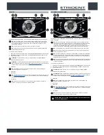
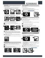
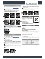


Upon request, the machine can be fitted with the VACUUM WAND system that vacuums up the
detergent solution more accurately.
To activate it, proceed as follows.
1. Using the DS selector on the control display (
Fig.1
), select the “transfer” program” (1).
2. Remove all the vacuum kit components from the storage compartment (
Fig.2
). To open the
storage compartment, use the handle (2) on the front of the control handlebars.
3. Assemble the steel extension tube (
Fig.3
).
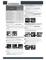
VACUUM WAND KIT
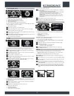
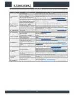
SOLUTION TANK OVERFLOW
The machine is equipped with a mechanical device (float) under the recovery tank lid that, when the
recovery tank is full, shuts off the air to the vacuum motor intake to protect it; the sound of the vacuum
motor will then be deeper.
If this is the case, proceed as follows:
1. From the DS control panel, select TRANSFER mode (A) (
Fig.1
).
2. Bring the machine to the designated place for emptying the recovery tank.
3.
Switch off the machine by making a quarter turn to the left with the key (1) of the main switch
(
Fig.2
).
4. Empty the recovery tank (see “
EMPTYING THE RECOVERY TANK
”).
NB
: the machine will only resume correct operation after the next start-up.
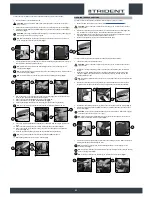
SMART DRYING SYSTEM
The machine has a function called “SMART DRYING”: shifting from the program that includes drying
(scrubbing with drying, or drying only) to the transfer program, this function delays the rise of the
squeegee coupling for max. 10 seconds, until the machine has moved another 3 metres.
NB
: as long as this function is active, the control display will visualise the relative screen
(
Fig.1
).
NB
: when the function terminates, the control display will visualise the relative screen (
Fig.2
)
and the actuator will bring the squeegee to its idle position.
NB
: to annul this function, press the “X” key on the screen (
Fig.1
).
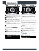
4. Connect the vacuum tube (4) to the extension tube (3) (
Fig.4
).
5. Insert the vacuum brush (5) in the extension tube (3) (
Fig.5
).
6. Remove the vacuum tube (6) from the sleeve (7) in the squeegee body (
Fig.6
).
7. Connect the wand kit vacuum tube (4) to the squeegee vacuum tube (5) (
Fig.7
).
8. Activate the vacuum control kit by pressing the button (7) (
Fig.8
).
NB
:
as soon as the button (7) is pressed, the LED on it will light up (
Fig.8
).
NB
:
as soon as the button (7) on the control display is pressed, the symbol (8) will appear
(
Fig.9
).
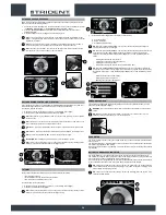
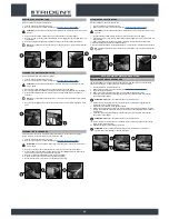
ALARM SCREEN
When an error occurs, the symbol (1) is displayed in the information field (
Fig.1
). It remains visible
until the error has been resolved.
The “ERROR” window will also be superimposed on the screen (
Fig.2
). It shows the alarm number,
the membership group, and a brief description.
When an error occurs, proceed as follows:
1. Stop the machine and press the button (2) (
Fig.2
).
2.
If the error persists, switch off the machine and wait at least ten seconds before switching it back
on.
NB
: to close the error screen, press the button (3) (
Fig.2
).
3. If the error persists, contact your nearest service centre.
NB
: the symbol (1) (
Fig.1
) remains visible until the error has been resolved.
NB
: if the machine is fitted with the HFM (HILLYARD FLEET MANAGEMENT) system, it will
send an e-mail to the affiliated service centre.
4.
Switch off the machine by turning the key (2) of the main switch to the left (
Fig.3
). Remove the
key from the instrument panel.
5. Carry out all the procedures listed in “RECOMMENDED PERIODIC MAINTENANCE” (in the “AT
THE END OF THE WORK” column).
6. Insert the key (2) in the main switch on the control panel. Set the main switch to “I”, turning the
key (2) to the left (
Fig.4
).
7. When you push the dead man's lever (1) (
Fig.2
), the machine will begin to move.
8. Take the appliance to the designated machine storage place.
ATTENTION
: park the machine in an enclosed place, on a flat surface, and at a safe distance
from any objects that could either damage it or be damaged due to contact with the machine
itself.
9. Make sure the machine is in a safe condition (see “
MACHINE SAFETY MEASURES
”).
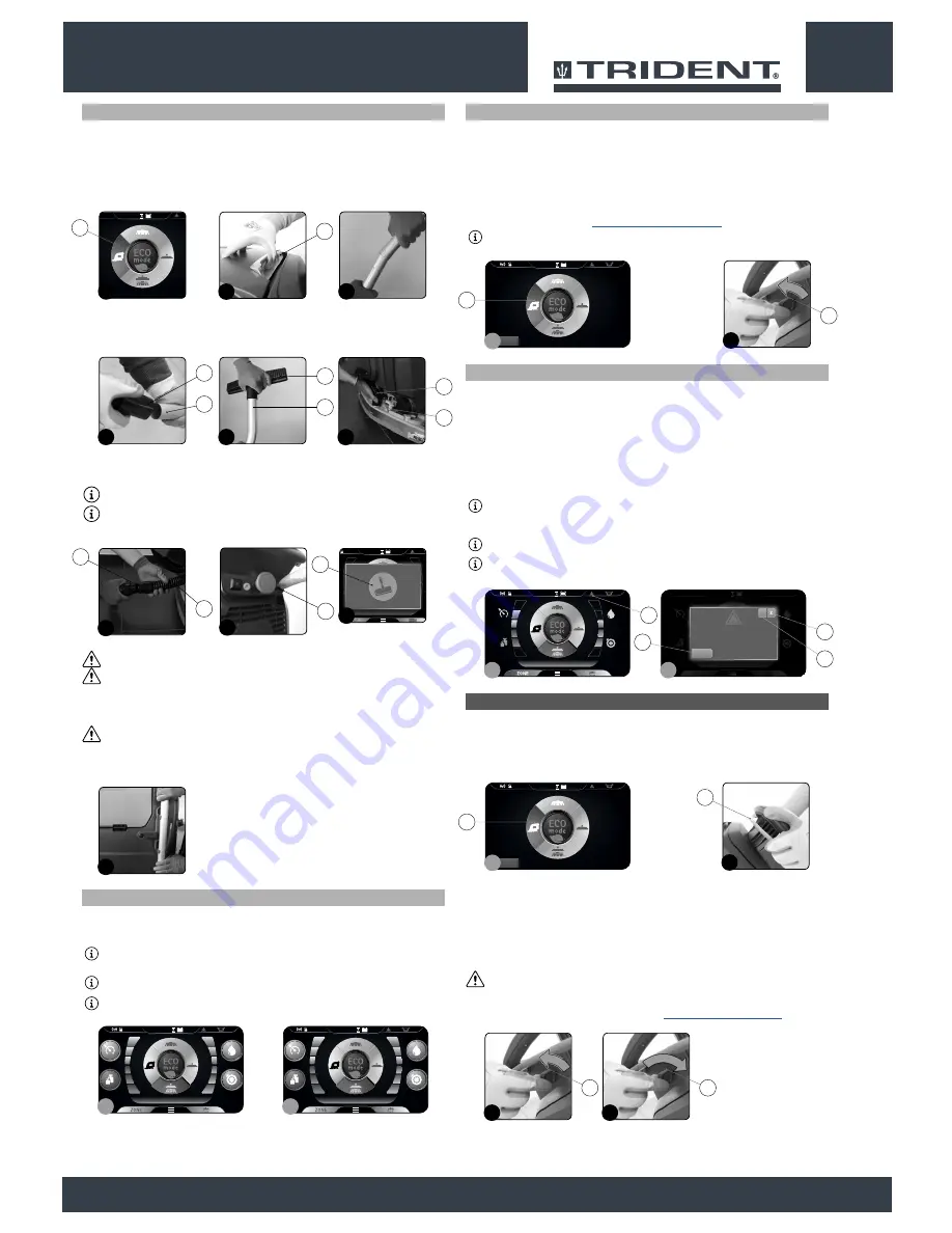
At the end of the work, and before carrying out any type of maintenance, perform the following
operations:
1. From the DS control panel, select TRANSFER mode (A) (
Fig.1
).
2. When you push the dead man's lever (1) (
Fig.2
), the machine will begin to move.
3. Take the appliance to the dedicated dirty water drainage area.
AT THE END OF THE WORK
WARNING
:
never pick up solid matter such as dust, cigarette stubs, paper, etc.
CAUTION
:
never collect gases, explosive/inflammable liquids or powders, nor acids and
solvents! These include gasoline, paint thinners and fuel oil (which, when mixed with the
vacuum air, can form explosive vapours or mixtures), and also non-diluted acids and solvents,
acetones, aluminium and magnesium powders. These substances may also corrode the
materials used to construct the machine.
CAUTION
:
if the machine is used in dangerous areas (e.g. petrol stations), the relative safety
standards must be observed. It is forbidden to use the machine in environments with a
potentially explosive atmosphere.
12.
After completing the task, the wand kit can be fixed in the side support on the machine (
Fig.13
).
21
OFFICE
0000.00
100%
ECO mode
0000.00
100%
Italiano
English
Spanish
French
German
Allarme 1
Gruppo
Descrizione
Reset
?
1
2
1
2
3
4
MANUAL
0000.00
100%
MANUAL
0000.00
100%
1
2
4
4
3
6
5
5
5
3
6
2
2
3
Back
0000.00
100%
1
1
7
4
5
8
7
0000.00
100%
9
8
13
Back
0000.00
100%
1
A
2
2
3
4
2
2
Back
0000.00
100%
1
A
2
1


