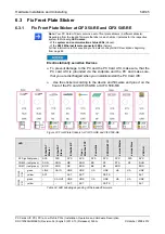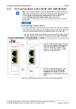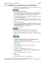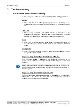
LED Descriptions
68/145
PC Cards cifX PCI, PCIe, Low Profile PCIe | Installation, Operation and Hardware Description
DOC120204UM36EN | Revision 36 | English | 2012-10 | Released | Public
© Hilscher, 2008-2012
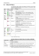
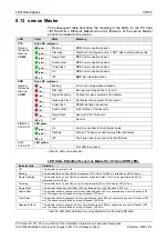
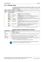
8.4 EtherCAT
Master
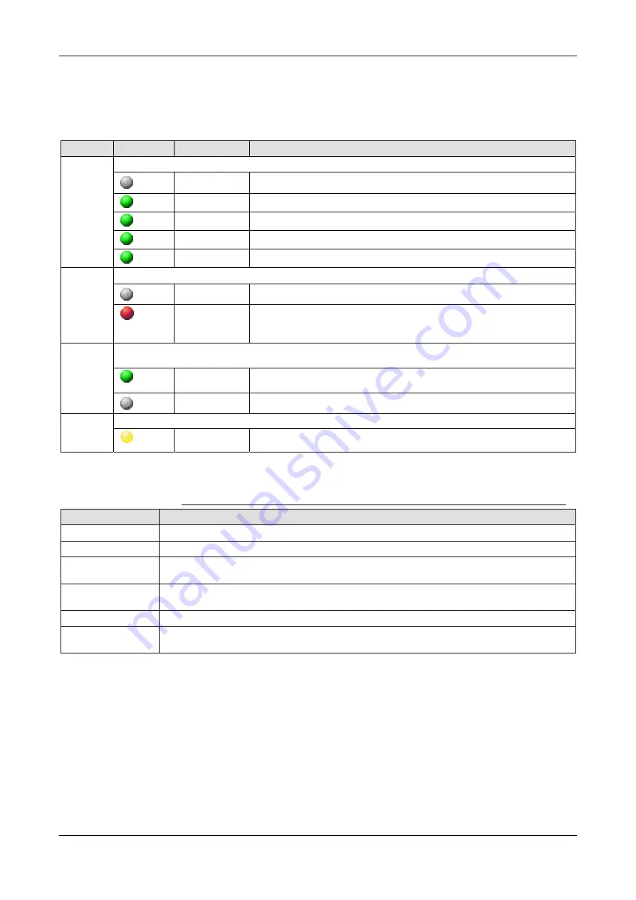
The subsequent table describes the meaning of the LEDs for the PC Card
cifX Real-Time Ethernet Master when the firmware of the EtherCAT Master
protocol is loaded to the device.
LED
Color
State
Meaning
Duo LED red/green
(off)
Off
INIT
: The device is in state INIT
(green)
Blinking
PRE-OPERATIONAL
: The device is in PRE-OPERATIONAL state
(green)
Flickering
BOOT
: Device is in Boot mode
(green)
Single Flash
SAFE-OPERATIONAL
: The device is in SAFE-OPERATIONAL state
RUN
Name in
the
device
drawing:
COM 0
(green)
On
OPERATIONAL
: The device is in OPERATIONAL state
Duo LED red/green
(off)
Off
Master has no errors
ERR
Name in
the
device
drawing:
COM 1
(red)
On
Master has detected a communication error. The error is indicated in the
DPM
LED green
(green)
On
A link is established
LINK
/
RJ45
Ch0
(off)
Off No
link
established
LED yellow
ACT
/
RJ45
Ch0
(yellow)
Flashing
The device sends/receives Ethernet frames
Table 40: LEDs EtherCAT Master
LED State Definition for EtherCAT Master for the RUN and ERR LEDs
Indicator state
Definition
On
The indicator is constantly on.
Off
The indicator is constantly off.
Blinking
The indicator turns on and off with a frequency of 2,5 Hz: on for 200 ms, followed by off for
200 ms.
Flickering
The indicator turns on and off with a frequency of approximately 10 Hz: on for approximately
50 ms, followed by off for 50 ms.
Single Flash
The indicator shows one short flash (200 ms) followed by a long off phase (1,000 ms).
Double Flash
The indicator shows a sequence of two short flashes (each 200 ms), separated by a short off
phase (200 ms). The sequence is finished by a long off phase (1,000 ms).
Table 41: LED State Definition for EtherCAT Master for the RUN and ERR LEDs

