Device Drawings
47/154
PC Cards cifX PC/104 | Installation, Operation and Hardware Description
DOC120206UM42EN | Revision 42 | English | 2014-12 | Released | Public
© Hilscher, 2008-2014
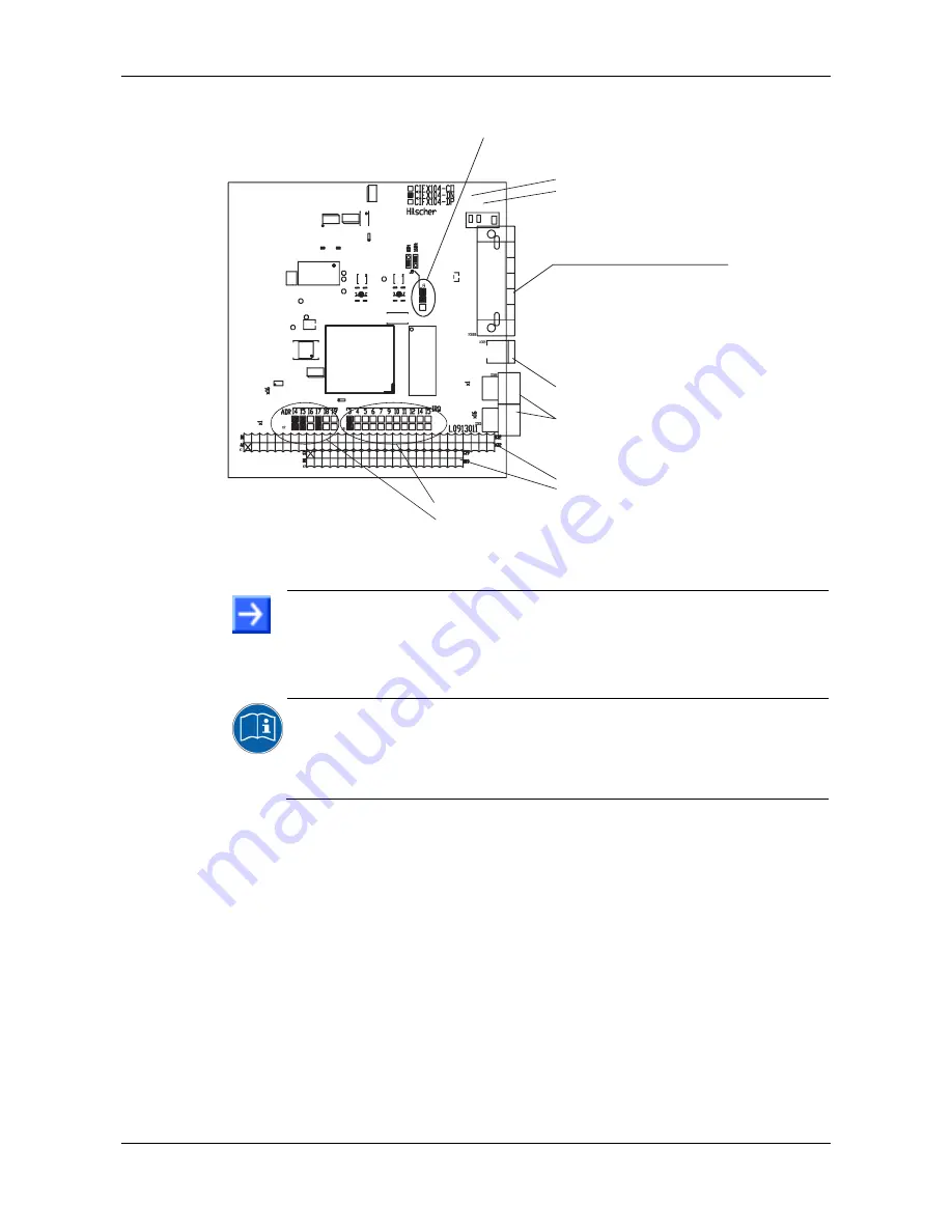
5.1.10 CIFX 104-DN-R
5
4
3
2
1
(x1)
(x16)
System LED
(gelb/grün) /
(yellow/green)
Modulnetzwerkstatus-LED
(rot/grün) /
Module Network Status LED
(red/green)
DeviceNet-Schnittstelle
COMBICON-Stecker (X360B, 5-polig)
DeviceNet Interface
COMBICON male Connector (X360B, 5 pin)
Mini-B-USB-Buchse /
Mini B USB Plug
(X305, 5-polig /
5 pin
)
Drehschalter Geräteadresse /
Rotary Switch Device Addres
s
(ohne Funktion /
without function
)
PC/104 Bus
(X1, 64-polig /
64 pin
)
(X2, 40-polig /
40 pin
)
SYS
MN
S
Interrupt-Steckbrücke /
Interrupt Jumper
(J8, 11-polig /
11 pin
)
Adresssteckbrücke /
Address Jumpers
(J7, 7-polig /
7 pin
)
Standardeinstellungen Steckbrücken /
Default Jumper Settings
Steckbrücke Datenbusbreite 8 Bit und 16 Bit
(J9, im Bild Einstellung Steckbrücke für 16 Bit)
Data Bus Width Jumpers 8 Bit and 16 Bit
(
J9,
Jumper Settings for 16 Bit shown)
Figure 11: CIFX 104-DN-R
Note:
In
Interrupt Mode
(IRQ = Interrupt Request) exactly one jumper must
be set. If no jumper is set, the PC card cifX works in
Polling Mode
.
For further details refer to
Table 23: Starting Address and Interrupt for
16 KByte Dual-Port Memory
on page 57.
For the pin assignment of the
PCI/104
bus X1/X2
refer to section
Pin
Assignment for PC/104 Bus
on page 96.
For further information on the
Mini-B USB
Connector refer to section
Mini-B USB Connector (5 Pin)
on page 91.


