background image

Parameterization 

59/98 

SmartWire-DT Gateway | EU5C-SWD-ETHERCAT  
DOC140901UM01EN | Revision 1 | English | 2015-03 | Released | Public  

© Hilscher 2015 


The EtherCAT

®

 master loads this configuration data into the gateway via 

SDOs when the gateway is in state 

Pre-Operational

.  


Also, the device parameters (

Parameters

) of sub index 

22

 are loaded into 

the corresponding SmartWire-DT device, if the device is an I/O module (the 
purpose of the device parameters is to configure the sensors of I/O 
modules). 
The module ID (

Product code

) of sub index 

06 

and the configuration data 

(

CFG

) of sub index 

20 

are needed by the gateway for identification and 

configuration purposes and must not be changed. The device options


(

Options

) of


sub index 

21 

and the device parameters (

Parameters

) of 

sub index 

22 

on the other hand can be edited if necessary. This is 

described in the following sections.  

9.3.2 

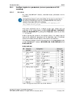
Configuring device options of SmartWire-DT devices in 
TwinCAT 

9.3.2.1 

Overview 

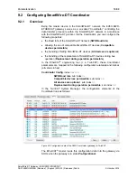
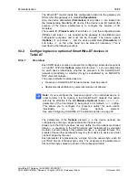
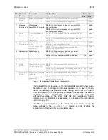
Each SWD device carries an element for configuring certain device options 
in TwinCAT. With this 

Options 

element (sub index 

21

), you can determine 

for each device individually, whether its presence in the SmartWire-DT 
network is mandatory or whether it may be substituted by an M22-SWD-
NOP universal module.  
The preset defaults for all devices are: 

  Presence in SmartWire-DT network: device must be present 

  Replacement/substitution by universal module: not allowed 


Note:

 If you reconfigure the “presence option” of an individual device in 

order to allow it to be missing in the SmartWire-DT network, this option 
will only be effective if the 

All Modules Optional

 (index 

0x2100:08)


parameter of the Coordinator is being kept at its default 

0x00 

setting. 

This allows you to configure the “presence option” for each device 
individually in its device options element.
See also 

Configuring SmartWire-DT Coordinator

 section on page 53. 


The parameters of the 

Options

 element (i. e. the device options) are 

configured by entering a single hexadecimal options byte.   
Please note that this byte does not only define the two options mentioned 
above (i. e. presence in the SWD network and replacement by universal 
module), but also defines other parameters like e. g. payload formats. The 
presets of these other parameters may vary from device to device and must 
not be changed by the user.  


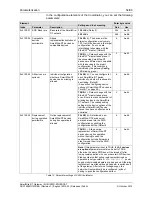
Each parameter is represented by a single bit in the options byte, each bit 
set TRUE has an individual byte value. The assignment of parameters to 
bits and their byte values are shown in the subsequent table: 

Summary of Contents for EU5C-SWD-ETHERCAT

Page 1: ...User Manual SmartWire DT Gateway EU5C SWD ETHERCAT Hilscher Gesellschaft für Systemautomation mbH www hilscher com DOC140901UM01EN Revision 1 English 2015 03 Released Public ...

Page 2: ...otes 13 1 5 3 Exclusion of liability 14 1 5 4 Warranty 14 1 5 5 Export regulations 15 1 5 6 Registered trademarks 15 2 SAFETY 16 2 1 General note 16 2 2 Intended use 16 2 3 Personnel qualification 16 2 4 References safety 16 2 5 Safety instructions to avoid personal injury 17 2 5 1 Electrical shock hazard 17 2 5 2 Danger of unintended starting up of machines 17 2 6 Safety instructions to avoid pro...

Page 3: ... GATEWAY 33 7 1 Safety messages 33 7 2 Mounting gateway 34 7 2 1 Mounting gateway onto top hat rail 34 7 2 2 Removing gateway from top hat rail 36 7 3 Connecting gateway to power supply 37 7 4 Connecting SmartWire DT 39 7 5 Connecting EtherCAT 40 7 6 EMC conformant wiring of the network 41 8 CONFIGURING GATEWAY 42 8 1 Configuring SmartWire DT network in gateway creating target configuration 42 8 1...

Page 4: ...10 3 Write request writing data in an SWD Slave 78 10 3 1 Activating write request 78 10 3 2 Querying the state of the write request 79 10 3 3 Example of a write request 80 10 4 Error messages emergency telegrams 82 10 4 1 Overview 82 10 4 2 Diagnosis code 82 10 4 3 Error flags 83 11 UPDATING FIRMWARE WITH TWINCAT SYSTEM MANAGER 84 11 1 Overview 84 11 2 Prerequisites 84 11 3 Step by step instructi...

Page 5: ...This manual is intended for automation technicians and engineers Detailed knowledge of the EtherCAT Real Time Ethernet protocol is presumed In addition readers should also be familiar with the TwinCAT System Manager and the SmartWire DT system IMPORTANT To avoid personal injuries or damage of electrical devices please read this manual carefully before installing and using the EU5C SWD ETHERCAT Gat...

Page 6: ...t Notes operation instructions and results of operation steps are marked as follows Notes Important important note Note note note where to find further information Operating Instructions 1 Operating step 2 Operating step and Operating instruction Results Result For a description of the labeling of Safety Messages see Labeling of safety messages section on page 20 ...

Page 7: ...mware Firmware version EU5C SWD ETHERCAT EtherCAT slave 9233 922 3 E030F0U0 nxf 1 0 x x Table 2 Reference to hardware and firmware Software tools This manual refers to the following software versions Software Manufacturer Version SWD Assist Eaton 2 xx TwinCAT System Manager Beckhoff Automation GmbH 2 11 Table 3 Reference to software tools Drivers This manual refers to the following driver versions...

Page 8: ...SmartWire DT EU5C SWD ETHERCAT Downloads Software Note The TwinCAT System Manager used in the commissioning example in this document is not included on the product DVD TwinCAT can be obtained from the Beckhoff Automation GmbH 1 3 1 Contents of the product DVD The SmartWire DT Gateway Solutions product DVD contains software for all types of SmartWire DT gateways Depending on the gateway type you ar...

Page 9: ...vers SWD Assist software Folder SWD Assist Wizard for installing the software available on the DVD and for downloading the latest version of the SWD Assist software from the internet Folder Setup Installation program for Ethernet Device Configuration Tool Folder EnDeviceCfg Installation program setup exe and INF and CAT files for Windows USB driver Folder USB Driver Table 6 Directory of the produc...

Page 10: ... for already installed software components which e g might have been installed for an earlier project and lists the missing components accordingly The following options might be offered USB Driver installs USB driver for Windows on your PC Download Center SWD Assist manual update connects your browser to a web page where you can download the latest version of the SWD Assist software SWD Planning S...

Page 11: ...nnect the gateway via USB for the first time to a PC running under Windows XP the Found New Hardware Wizard opens Answer the question Can Windows connect to Windows Update with No not this time Then click Next button If you have already carried out the setup of the USB driver as recommended you can ignore the wizard s request to insert a CD or floppy disk Answer the What do you want the wizard to ...

Page 12: ...MN05006001Z EN Documentation english 3 SmartWire DT SmartWire DT Units MN05006001Z_EN pdf SmartWire DT The System Information on function installation commissioning and diagnostics of the SmartWire DT system Eaton 02 11 MN05006002Z EN Documentation english 3 SmartWire DT SmartWire DT The System MN05006002Z_EN pdf SWD Assist Online help Online help for SWD Assist planning software Eaton Included in...

Page 13: ...nd the documentation were created for the use of the products by qualified experts however errors cannot be ruled out For this reason no guarantee can be made and neither juristic responsibility for erroneous information nor any liability can be assumed Descriptions accompanying texts and documentation included in the user manual do not present a guarantee nor any information about proper use as s...

Page 14: ...or air traffic communication systems in life support systems in systems in which failures in the software could lead to personal injury or injuries leading to death We inform you that the software was not developed for use in dangerous environments requiring fail proof control mechanisms Use of the software in such an environment occurs at your own risk No liability is assumed for damages or losse...

Page 15: ... You are obligated to comply with the regulations at your personal responsibility We wish to inform you that you may require permission from state authorities to export re export or import the product 1 5 6 Registered trademarks Adobe Reader is a registered trademark of Adobe Systems Incorporated EtherCAT is registered trademark and patented technology licensed by Beckhoff Automation GmbH Germany ...

Page 16: ...erCAT network 2 3 Personnel qualification The EU5C SWD ETHERCAT Gateway must be installed configured and removed by qualified personnel only Job specific technical skills for people professionally working with electricity must be present concerning the following issues Safety and health at work Mounting and connecting of electrical equipment Measurement and analysis of electrical functions and sys...

Page 17: ... housings 2 5 2 Danger of unintended starting up of machines Install automation devices and related operating elements in a way that they are well protected against unintentional operation Emergency stop devices complying with IEC EN 60204 1 must be effective in all operating modes of the automation devices Unlatching the emergency stop devices must not cause restart You must take safety precautio...

Page 18: ...troyed if the polarity of the power supply is reversed The functional earth FE must be connected to the protective earth PE or to the potential equalization The system installer is responsible for implementing this connection Connecting cables and signal lines should be installed so that inductive or capacitive interference does not impair the automation functions Suitable safety hardware and soft...

Page 19: ...its normal operation Therefore adhere to the necessary safety precautions for components that are vulnerable to electrostatic discharge when you install or remove the gateway Follow the guidelines listed hereafter when you handle the gateway Touch a grounded object to discharge potential static before you handle the gateway Wear an approved grounding wrist strap If possible use a static safe works...

Page 20: ... warning or principle Warning of personal injury Warning of property damage by electrostatic discharge Principle Disconnect the power plug Table 8 Safety symbols and sort of warning or principle Signal word Meaning Meaning USA Indicates a direct hazard with high risk which will have as consequence death or grievous bodily harm if it is not avoided Indicates a hazardous situation which if not avoid...

Page 21: ...ce or PLC of the super ordinate EtherCAT network The gateway acts as master a k a Coordinator in the SmartWire DT network on the one hand and on the other hand as modular slave in the EtherCAT network It thereby presents each connected SmartWire DT participant as individual module to the EtherCAT master The cyclic process data is exchanged transparently between both networks 1000 Bytes of process ...

Page 22: ...wrong slave type is determined it will not go into operation If the actual configuration complies with the target configuration the gateway gets ready for EtherCAT and waits for the EtherCAT configuration The gateway checks the project configuration which it receives from the EtherCAT master against the target configuration Discrepancies between target and project configuration are indicated by th...

Page 23: ... gateway can be diagnosed by connecting the SWD Assist software to the Mini USB interface For further information please refer to the SWD Assist online help The EtherCAT protocol also provides diagnostic functions For further information see section Error messages emergency telegrams on page 82 3 5 Firmware and device description files The EU5C SWD ETHERCAT Gateway is shipped with its most recent ...

Page 24: ...y providing power for the SmartWire DT system must feature a PELV power feed module protective extra low voltage Ensure a reliable electrical isolation of the low voltage for the 24 volt supply Only use power supply units complying with IEC 60364 4 41 VDE 0100 Part 410 or HD 384 4 41 S2 You must take safety precautions emergency switching off in the external circuitry of the EU5C SWD ETHERCAT and ...

Page 25: ...nection If any switching devices are also to be connected for example via the DIL SWD 32 001 002 SmartWire DT slaves a 24 V DC supply will also be required at the AUX power connection This provides the supply for activating the contactor coils This supply must be protected by an automatic circuit breaker 3A gG gl or 3 A miniature circuit breaker with a Z characteristic If switching devices with an...

Page 26: ...Picture Connectors and LEDs 5 1 Device picture 24 V power supply POW EtherCAT interface RJ45 LEDs EtherCAT communication status see subsequent section for details Mini USB interface Configuration button LEDs gateway functions see subsequent section for details 24 V power supply AUX SmartWire DT connection plug 8 pole Figure 2 Front view EU5C SWD ETHERCAT gateway ...

Page 27: ...and meaning of the LEDs 5 2 1 Positions of the LEDs POW System status APL Application status Config Configuration status SWD SmartWire DT status RUN EtherCAT bus status ERR EtherCAT bus error L A LINK Activity for channel 0 Receive Transmit RX TX for channel 0 L A LINK Activity for channel 1 Receive Transmit RX TX for channel 1 Figure 3 LEDs EU5C SWD ETHERCAT Gateway ...

Page 28: ...hange between gateway and PLC via EtherCAT is possible green Blinking The project configuration does not comply with the target configuration but is compatible with it Data exchange between gateway and PLC via EtherCAT is possible red On The project configuration and the target configuration are not compatible Data exchange between gateway and PLC via EtherCAT is not possible Config Configuration ...

Page 29: ...ble due to register or object settings red Single flash Unsolicited State Change Slave device application has changed the EtherCAT state autonomously Parameter Change in the AL status register is set to 0x01 change error Example Synchronization Error device enters Safe Operational automatically red Double flash Application Watchdog Timeout An application watchdog timeout has occurred Example Sync ...

Page 30: ...re shows the pinning of the Real Time Ethernet EtherCAT interface of the Gateway Figure 4 Pinning of the Ethernet interface RJ45 Pin Signal Description 1 TX Transmit Data 2 TX Transmit Data 3 RX Receive Data 4 TERM 5 TERM Bob Smith Termination 6 RX Receive Data 7 TERM 8 TERM Bob Smith Termination Table 11 Ethernet interface channel 0 and channel 1 pin assignment RJ45 Note The Ethernet interface su...

Page 31: ...th a device type label which provides the following information Version of firmware at time of delivery Information on power supply for switching devices AUX Information on power supply for Gateway and Smart Wire DT slaves POW Information on wire gauge of power supplies Operating ambient temperature Device type name Part number Hardware revision number Serial number Figure 5 Device type label EU5C...

Page 32: ... page 40 2 Configure gateway Chapter Configuring gateway on page 42 2 1 Configure SmartWire DT network in gateway Section Configuring SmartWire DT network in gateway on page 42 2 2 Import device description files in EtherCAT engineering tool TwinCAT System Manager 2 3 Configure gateway in EtherCAT engineering tool Section Configuring gateway in TwinCAT on page 45 3 Configure SmartWire DT devices i...

Page 33: ... units that are live Electrostatic Sensitive Device The gateway is sensitive to electrostatic discharge which can cause internal damage and affect its normal operation Therefore adhere to the necessary safety precautions for components that are vulnerable to electrostatic discharge when you install or handle the gateway Do not touch the metal pins of the connectors of the gateway Touch a grounded ...

Page 34: ...way can be clamped to the rail Figure 6 Mounting principle of the gateway 7 2 1 Mounting gateway onto top hat rail To mount the gateway onto the top hat rail proceed as follows Make sure that the gateway is disconnected from any power supply Cover or enclose neighboring units that are live Tilt the gateway slightly and hook it into the upper railing from above thereby pushing down the gateway with...

Page 35: ...g the gateway downwards and tilt it back into vertical position thereby hooking the gateway into the lower railing Figure 8 Hook gateway to lower railing Let go of the gateway The spring inside the bolt automatically pushes the gateway upwards into the railings thereby fixing the gateway to the top hat rail Figure 9 Gateway is clamped to top hat rail ...

Page 36: ...ay from the top hat rail proceed as follows First disconnect the power plugs from the gateway Make sure that the power supply is off at the gateway Cover or enclose neighboring units that are live Push down the gateway with slight force to overcome the resistance of the spring in the bolt then unhook the gateway first from the lower railing and then from the upper railing Figure 10 Unhook gateway ...

Page 37: ... safety precautions emergency switching off in the external circuitry of the EU5C SWD ETHERCAT Gateway and any power modules type EU5C SWD PF1 1 or EU5C SWDPF2 1 that are used To do so plan to switch off the power supply to the contactor coils AUX Important Please take into consideration the total power consumption of your SmartWire DT network and if necessary plan for an additional feeder module ...

Page 38: ...or activating the contactor coils This supply must be protected by an automatic circuit breaker 3A gG gl or 3 A miniature circuit breaker with a Z characteristic If switching devices with an activation power greater than 3 A are connected an additional feeder module EU5C SWD PF1 or EU5C SWD PF2 must be used Potential conditions between the components The entire SmartWire DT system operates on a co...

Page 39: ...es of type SWD4 3 5 10 F8 24 2S Figure 12 Connecting SmartWire DT to gateway Switch off the power supply before you are reconnecting slaves in the SmartWire DT system or reconnecting the ribbon cable connection Otherwise the SmartWire DT slaves can be destroyed Note Detailed instructions on adapting the SmartWire DT external device plug SWD4 8SF2 5 to the 8 pole Smart Wire DT cable are provided in...

Page 40: ...nt Please observe the following notes on EtherCAT cabling Use shielded Ethernet cables that meet the requirements of at least category 5 Cat 5 according to EN 50173 or ISO IEC 11801 Do not use hubs in an EtherCAT network Do not use switches in a productive system Use a switch for diagnostic purpose only and only between EtherCAT master and first EtherCAT slave device 100 MBit s Full Duplex A switc...

Page 41: ...f suitable EMC measures These include EMC conformant system configuration EMC compliant cable routing Measures that do not allow the occurrence of large differences in potential and correct installation of the EtherCAT system cables connection of the bus connectors etc The effects of electromagnetic interference can be significantly reduced by fitting a shield For more detailed information on this...

Page 42: ...d to the SWD bus and store it as target configuration Reading and storing the SmartWire DT network configuration takes place by pressing the configuration button on the gateway for the position of the configuration button see figure Front view EU5C SWD ETHERCAT gateway on page 26 All SmartWire DT slaves are re addressed in ascending order by this process This process should only take place in the ...

Page 43: ...D LED see Positions of the LEDs section on page 27 If a SmartWire DT slave has failed the SmartWire DT network can still be operated with the remaining slaves depending on the settings in the planned project configuration even after a repeated power up of the gateway The failure is reported to the application 8 1 2 Prerequisites Prerequisites for reading in the SmartWire DT configuration are All S...

Page 44: ...D SWD LED on the gateway begins to flash orange The SmartWire DT status LEDs on the SmartWire DT slaves also flash All slaves are addressed in sequence the complete configuration is stored retentively as gateway target configuration Hazard of device damage by disruption of voltage supply while creating target configuration Do not interrupt the voltage supply while creating the target configuration...

Page 45: ...neering tool Important Please note that data exchange between the gateway and the EtherCAT network can only take place after a SmartWire DT network has been connected and configured in the gateway see section Configuring SmartWire DT network in gateway creating target configuration on page 42 8 2 2 Configuring gateway in TwinCAT This section describes how to create the project configuration for th...

Page 46: ..._XXXXXXXX xml files only if the Smart Wire DT network includes partner devices by Phoenix or Wöhner Copy the files to the TwinCAT Io EtherCAT directory of the TwinCAT installation on your configuration PC The device description files of the gateway and the SmartWire devices are now available in the TwinCAT System Manager 2 Start TwinCAT In the Windows start menu select All Programs TwinCAT System ...

Page 47: ...rk adapters The TwinCAT Driver for Real Time Ethernet provides hard RTE support for EtherCAT applications but can only be used with Intel based network adapters Adapters on your PC recognized by TwinCAT and supported by this driver are listed under Compatible devices see picture above The TwinCAT Real Time Ethernet Intermediate Driver can be used for network adapters without an Intel chip set but ...

Page 48: ...splayed as TwinCAT Ethernet Adapter under Installed and ready to use devices Figure 16 Installing TwinCAT Ethernet adapter 2 Close the dialog window by clicking on the red button in the upper right corner of the dialog window 4 Scan for EtherCAT devices In the navigation tree of the TwinCAT System Manager select I O Devices element then choose Scan Devices entry from the context menu Figure 17 Sca...

Page 49: ... scan Acknowledge with OK The New devices found dialog window opens Figure 19 New devices found dialog window Activate the check box in front of the device which you want to use as EtherCAT master device then click OK The New devices found dialog window closes and the selected master device is inserted in the navigation tree below the I O Devices element Also the System Manager asks you to Scan fo...

Page 50: ...ll be found and displayed as Box x EU5C SWD ETHERCAT below the master device in the navigation tree The SmartWire slaves connected to the gateway will also be found and added to the gateway entry as subordinate modules The System Manager asks you to activate the Free Run mode Figure 21 EU5C SWD ETHERCAT Gateway found as new box Activate the Free Run mode by clicking Yes In Free Run mode the TwinCA...

Page 51: ...ule 1 Module 2 etc Figure 22 EU5C SWD ETHERCAT Gateway process data 1 Select the gateway in the navigation tree then open the Online tab in the main window When Free Run mode is active the Current State field in the State Machine area displays OP state operational The lower area of the main window shows the I O data of the SmartWire slaves Create output data at one of the SmartWire slaves In this ...

Page 52: ...e DT device is mapped to object RxPDO index 0x1600 sub index 0x00 and following Input data of a SmartWire DT device is mapped to object TxPDO index 0x1A00 Sub index 0x00 and following The EtherCAT master adds all configured PDOs to the RxPDO Assign Object index 0x1C12 and to the TxPDO Assign Object index 0x1C13 The EtherCAT master loads this configuration data into the gateway via SDOs when the ga...

Page 53: ...le the handling of failing SmartWire DT devices All devices are optional the handling of the replacement of SmartWire DT devices during bus operation Replacement during operation permissible In the EtherCAT engineering tool i e TwinCAT these Coordinator parameters are mapped to the following configuration elements and indices all values in hex Coordinator Config index 0x2100 SWD Baud rate sub inde...

Page 54: ...dual configuration whether a SmartWire DT device can be missing is allowed TRUE 1 Data exchange with the EtherCAT master takes place even if there is a random number of missing devices in the SmartWire DT network The corresponding settings in the device options of the individual SmartWire DTdevice slaves thus have no effect and are overruled 1 0x01 FALSE 0 Not allowed new SmartWire DT devices must...

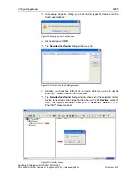
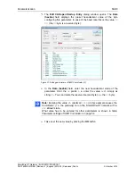
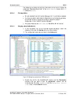
Page 55: ...on in the TwinCAT System Manager 9 2 3 Step by step instructions In the navigation tree of the TwinCAT System Manager select the gateway then open the Startup tab in the main window The configuration elements are listed in the Startup tab Figure 26 Editing parameters of SWD Coordinator 1 Search the list for the configuration element of the Coordinator parameter that you want to edit A Coordinator ...

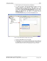
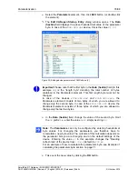
Page 56: ...te Figure 27 Editing parameters of SWD Coordinator 2 In the Data hexbin field enter the new hexadecimal value of the parameter Omit the 0x prefix i e enter the value 0xFA simply as string FA You can delete the reserved second byte i e the 00 byte Note Entering the value FA decimal 250 in this example causes the Coordinator i e the gateway to run the SmartWire DT network with a 250 kBaud s rate Wha...

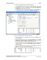
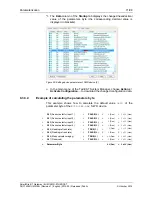
Page 57: ... 2015 The Data column of the Startup tab displays the changed value the corresponding decimal value is displayed in brackets behind the hexadecimal value Figure 28 Editing parameters of SWD Coordinator 3 In the main menu of the TwinCAT System Manager choose Actions Activate Configuration to download the changed configuration data ...

Page 58: ... configuration the EtherCAT engineering tool i e TwinCAT maps these data sets to the following elements all values in hex Device Module 1 index 0x8000 Module ID Product code sub index 06 Configuration data CFG sub index 20 Device options Options sub index 21 Device parameters Parameters sub index 22 Device Module 2 index 0x8010 Module ID Product code sub index 06 Configuration data CFG sub index 2...

Page 59: ...e DT network is mandatory or whether it may be substituted by an M22 SWD NOP universal module The preset defaults for all devices are Presence in SmartWire DT network device must be present Replacement substitution by universal module not allowed Note If you reconfigure the presence option of an individual device in order to allow it to be missing in the SmartWire DT network this option will only ...

Page 60: ...rsal module TRUE 1 Device can be replaced by universal module 16 0x10 5 Reserved Bit is not used 0 0 0x00 FALSE 0 Device does not have different data profiles 0 0x00 6 Profile Device Support of data profiles Do not change this parameter TRUE 1 Device supports different data profiles and requires the Coordinator to set the profile accordingly 64 0x40 FALSE 0 Device does not have acyclic data object...

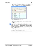
Page 61: ...roject features the DIL SWD 32 001 SmartWire DT contactor module 9 3 2 3 Step by step instructions In the navigation tree of the TwinCAT System Manager select the gateway then open the Startup tab in the main window The configuration elements are listed in the Startup tab Figure 30 Editing device options of SWD device 1 Search the list for the SmartWire DT device and the Options element that you w...

Page 62: ...2 simply as string 12 Note Individual parameters of the Options element i e the device options can only be configured by entering a single hexadecimal options byte For changing one or several parameters you therefore have to recalculate the whole options byte of the device The outcome of this calculation depends on the parameter bits you have changed and on the default settings of the device Enter...

Page 63: ...ring a single hexadecimal options byte The logically ORed byte values of the individual bits representing the configuration parameters amount to the value of the options byte To change an individual parameter you have to look at the bit representing this parameter After having set the bit on TRUE in order to activate the corresponding parameter respectively the desired function you have to logical...

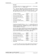
Page 64: ...0 Dez 0x00 Hex Options Byte 2 Dez 0x02 Hex This options byte means for the DIL SWD 32 001 device that it must be present in the current bus configuration Bit 1 TRUE but that is has no extended parameters Bit 0 FALSE and does not use CRC8 with its cyclic input data Bit 2 FALSE etc If you now want to allow the substitution of the device within the SmartWire DT bus by an universal module you have to ...

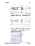
Page 65: ... that it may be replaced by an universal module you have to set Bit 1 to FALSE and Bit 4 to TRUE The calculation for this looks as follows Bit 0 Extended parameters FALSE 0 0 Dez 0x00 Hex Bit 1 Presence in SmartWire DT network FALSE 0 0 Dez 0x00 Hex Bit 2 Cyclic input data with CRC8 FALSE 0 0 Dez 0x00 Hex Bit 3 Format of payload data words FALSE 0 0 Dez 0x00 Hex Bit 4 Substitution by universal mod...

Page 66: ... You always have to look up the definite bit assignment of the parameter byte of individual devices in the latest documentation of the device s manufacturer The subsequent tables show the bit assignments of the Parameters bytes of the SmartWire DT devices EU5E SWD 4AX EU5E SWD 2A2A and EU5E SWD 4PT EU5E SWD 4AX Byte value Bit Parameter function Configuration Dez Hex FALSE 0 Voltage default 0 0x00 ...

Page 67: ...ector Input 2 TRUE 1 Current 2 0x02 FALSE 0 Voltage default 0 0x00 2 Actuator selector Output 1 TRUE 1 Current 4 0x04 FALSE 0 Voltage default 0 0x00 3 Actuator selector Output 2 TRUE 1 Current 8 0x08 Bit 5 Bit 4 Milli seconds FALSE 0 FALSE 0 20 ms 0 0x00 FALSE 0 TRUE 1 100 ms default 16 0x10 TRUE 1 FALSE 0 200 ms 32 0x20 4 5 Reading refresh rate TRUE 1 TRUE 1 500 ms 48 0x30 FALSE 0 off 0 0x00 6 Me...

Page 68: ...SE 0 PT1000 32 0x20 4 5 Sensor selection Input 3 TRUE 1 TRUE 1 NI1000 48 0x30 Bit 7 Bit 6 Sensor type FALSE 0 FALSE 0 Not used default 0 0x00 FALSE 0 TRUE 1 PT100 64 0x40 TRUE 1 FALSE 0 PT1000 128 0x80 6 7 Sensor selection Input 4 TRUE 1 TRUE 1 NI1000 192 0xC0 Table 17 Bit assignment of parameter byte 1 of EU5E SWD 4PT Byte 2 Byte value Bit Parameter Configuration Dez Hex Bit 1 Bit 0 Unit FALSE 0 ...

Page 69: ...g gateway in TwinCAT section on page 45 and have opened the project configuration in the TwinCAT System Manager The project features the EU5E SWD 4AX SmartWire DT I O module 9 3 3 3 Step by step instructions In the navigation tree of the TwinCAT System Manager select the gateway then open the Startup tab in the main window The configuration elements are listed in the Startup tab Figure 34 Editing ...

Page 70: ...A the Parameters element consists of two bytes of which you are allowed to change only the second byte In case of the EU5E SWD 4PT device the Parameters element consists of three bytes of which you are allowed to change only the last two bytes In the Data hexbin field change the value of the second byte Omit the 0x prefix i e enter the value 0x60 simply as string 60 Note The Parameters can only be...

Page 71: ...ownload the changed configuration data 9 3 3 4 Example of calculating the parameters byte This example shows how to calculate the default value 0x50 of the parameter byte of the EU5E SWD 4AX SWD device Bit 0 Sensor selector input 1 FALSE 0 0 Dez 0x00 Hex Bit 1 Sensor selector input 2 FALSE 0 0 Dez 0x00 Hex Bit 2 Sensor selector input 3 FALSE 0 0 Dez 0x00 Hex Bit 3 Sensor selector input 4 FALSE 0 0...

Page 72: ... 4AX on page 66 Bit 0 Sensor selector input 1 FALSE 0 0 Dez 0x00 Hex Bit 1 Sensor selector input 2 FALSE 0 0 Dez 0x00 Hex Bit 2 Sensor selector input 3 FALSE 0 0 Dez 0x00 Hex Bit 3 Sensor selector input 4 FALSE 0 0 Dez 0x00 Hex Bit 4 Reading refresh rate FALSE 0 0 Dez 0x00 Hex Bit 5 Reading refresh rate TRUE 1 32 Dez 0x20 Hex Bit 6 Mean value averaging TRUE 1 64 Dez 0x40 Hex Bit 7 Reserved FALSE 0...

Page 73: ...r from the SWD slave the EtherCAT master regularily queries the state of the task by sending SDO Upload Requests to the index 0x2200 sub index 2 object As long as the gateway has not yet received the answer from the SWD slave SmartWire DT communication is slower than EtherCAT communication the SDO Upload Confirmation conveys the Request State 1 in progress The EtherCAT master thus has to keep on s...

Page 74: ...Acyclical communication 74 98 SmartWire DT Gateway EU5C SWD ETHERCAT DOC140901UM01EN Revision 1 English 2015 03 Released Public Hilscher 2015 Figure 37 Conducting acyclical communication ...

Page 75: ...nt to read according to project configuration uint8 1 99 SWD Index SWD specific index of the SWD slave Determines which kind of data you want to read e g error counter or firmware version uint8 0 255 Request Type Type of request A read request must have the value 1 uint8 1 Length Maximum length of the expected response in bytes Must be at least as long as the SWD object in bytes uint8 1 120 Job ID...

Page 76: ... according to project configuration uint16 0 65535 Index Object index for acyclical communication uint16 0x2200 Sub index Index for SDO Upload uint8 0x02 Size Amount of data of the SDO Upload 10 Bytes n Data of SWD slave Slave Address Address of the SWD slave of which data has been read uint8 1 99 SWD Index SWD index of the data which has been read e g error counter or firmware version uint8 0 255...

Page 77: ...ress SWD Index Request Type Length Job ID Reserved Bytes 0x03 0x2200 0x01 0xA 0x05 0x7F 0x01 0x78 0x01 0x00 0x00 0x00 0x00 0x00 Table 22 Example SDO Download Request for a read request 10 2 3 2 Querying the state of the read request Querying the state of the read request The SDO Upload Request sent by the EtherCAT master to the gateway looks as follows Syntax Address Object index Sub index 0x03 0x...

Page 78: ...ndex Object index for acyclical communication uint16 0x2200 Sub index Index for SDO Download uint8 0x01 Size Amount of data of the SDO Download 10 Bytes n Data for SWD slave Slave Address Address of the SWD slave that you want to read according to project configuration uint8 1 99 SWD Index SWD specific index of the SWD slave Determines where to write the data to uint8 0 255 Request Type Type of re...

Page 79: ... Node ID of the gateway according to project configuration uint16 0 65535 Index Object index for acyclical communication uint16 0x2200 Sub index Index for SDO Upload uint8 0x02 Size Amount of data of the SDO Upload 10 Bytes Data of SWD slave Slave Address Address of the SWD slave of which data has been read uint8 1 99 SWD Index SWD index into which the data was written uint8 0 255 Request Type Typ...

Page 80: ...0x00 0x00 0x00 Table 29 Example SDO Download Request for a write request 10 3 3 2 Querying the state of the write request Querying the state of the write request The SDO Upload Request sent by the EtherCAT master to the gateway looks as follows Syntax Address Object index Sub index 0x03 0x2200 0x02 Table 30 Example SDO Upload Request for a write request Answer of the gateway in case of an unfinish...

Page 81: ... the acknowledgement from the SWD slave has arrived the SDO Upload Confirmation sent by the gateway to the EtherCAT master looks as follows Syntax Header Auftragsdaten Address Object index Sub index Size Slave Address SWD Index Request Type Length Job ID State Error Code 0x03 0x2200 0x02 0xA 0x05 0x7F 0x02 0x01 0x01 0x02 0x00000000 Table 32 Example SDO Upload Confirmation for a finished write requ...

Page 82: ...f SmartWire device Bit 7 Manufacturer specific error Unused bytes have value 0 Table 33 Structure of emergency telegram 10 4 2 Diagnosis code If Error Code 0x70XX module specific error is displayed byte 0 of the Additional Information field features a diagnostic code The ID of the SmartWire slave reporting the error is displayed in the second byte Address of the Error Code The subsequent table lis...

Page 83: ...e is present 5 13 0x20 6 14 0x40 2 7 15 0x80 0 16 0x01 Error SWD Mandatory SmartWire DT device is missing 1 17 0x02 Warning SWD Optional SmartWire DT device is missing 2 18 0x04 3 19 0x08 4 20 0x10 5 21 0x20 Error SWD No valid project configuration 6 22 0x40 3 7 23 0x80 0 24 0x01 Error SWD Short circuit in the 15V voltage supply of the SmartWire DT bus 1 25 0x02 Error SWD Internal error of the Sma...

Page 84: ...e firmware of the gateway Power failure during a writing process within the file system can cause severe malfunctioning of the device Note In case of a missing or defective firmware which is indicated by a green POW LED the regular firmware update process described in this chapter is not working In this case proceed as described in chapter Firmware recovery via HTTP on page 87 ff 11 2 Prerequisite...

Page 85: ...015 Figure 38 Online tab In the File Access over EtherCAT area of the Online tab click Download button The Windows file the selection dialog window opens Figure 39 Select Firmware In the Files of type drop down list select All Files then navigate to the directory where the firmware intended for download is stored Select E030F0U0 nxf file then click Open button ...

Page 86: ...ension Figure 41 Edit firmware name 2 Click OK button The download of the firmware is started The download process can take several minutes The progress of the download is indicated by a progress bar in the footer of the TwinCAT System Manager Hazard of device damage by disruption of voltage supply during firmware update Do not interrupt the voltage supply while downloading the firmware of the gat...

Page 87: ...eway in order to download the new firmware file via ordinary web browser If you do not know the exact IP address assigned to the gateway by the DHCP server you can use the Hilscher Ethernet Device Configuration Tool on your configuration PC included on the product DVD in order to read out the newly assigned IP address from the gateway The tool uses the netIDENT protocol to search for all Hilscher ...

Page 88: ...thernet network in which a DHCP server is active into one of the Ethernet RJ45 sockets labeled LAN1 IN or LAN2 OUT on the front side of the gateway Reconnect the gateway to the voltage supply Note The L A LINK Activity LEDs of the Ethernet RJ45 sockets remain dark when an Ethernet cable is plugged in while the backup firmware is running even if a successful IP communication with an local Ethernet ...

Page 89: ...ddress Note If the default IP address 0 0 0 0 is displayed the gateway has not yet received an IP address from a DHCP server Make sure that the gateway is connected to a subnet with an active DHCP server Then restart the gateway by briefly disconnecting the voltage supply while the Ethernet cable remains plugged in Wait a few seconds after reconnecting the voltage supply then click the Search Devi...

Page 90: ...ed in Internet Explorer 4 Select firmware file for download Click Browse button to open a dialog window for selecting the firmware file you want to download Navigate to the directory in which the firmware file is stored select the file then click Open Note The name of the firmware file for the EU5C SWD ETHERCAT gateway is E030F0U0 nxf Path and name of the selected file are displayed in the field n...

Page 91: ...n the validity of the firmware file is being checked by the system If the file fails the validity check an error message will be displayed If the file passes the gateway requests you to perform a reset in order to start the new firmware Figure 45 Reset after firmware download via HTTP as depicted in Internet Explorer 6 Perform reset Activate the checkbox in front of Please confirm to acknowledge t...

Page 92: ...lic Hilscher 2015 Click Submit button to start the reset After successful reset the following message is displayed Figure 46 Successful device reset message as depicted in Internet Explorer The POW system status LED at the gateway shows steady yellow light The new firmware has been loaded and the gateway is ready for operation ...

Page 93: ...068 2 27 Semi sinusoidal 15 g 11 ms 9 Shocks Drop to IEC EN 60068 2 31 Drop height 50 mm Ambient mechanical conditions Free fall packaged IEC EN 60068 2 32 Drop height 1 m Operating ambient temperature IEC 60068 2 25 55 C Condensation Prevent by suitable measures Storage 40 70 C Ambient climatic conditions Relative humidity non condensing IEC EN 60068 2 30 5 95 Pollution degree 2 Electrostatic dis...

Page 94: ...rotection against polarity reversal Yes Rated operational current I 111 mA with two participants Heat dissipation at 24 V DC 2 66 W with two participants Potential isolation between UPOW and 15 V SmartWire DT supply voltage No Bridging voltage dips 10 ms Repeat rate 1 s Supply voltage UPOW Status display POW LED Rated operational voltage Ue 15 V 3 max current Imax 0 7 A Note If contactors with a t...

Page 95: ... ERR duo color red green Connector socket 2 x RJ45 Connector plug RJ45 Ethernet EtherCAT network Potential isolation Yes Table 36 Technical data EU5C SWD ETHERCAT gateway 13 2 Technical data EtherCAT slave Parameter Description Maximum number of cyclic input data 800 bytes restricted by SWD Maximum number of cyclic output data 641 bytes restricted by SWD Maximum number of cyclic input output data ...

Page 96: ... process data 1 51 Figure 23 EU5C SWD ETHERCAT Gateway process data 2 51 Figure 24 Process data mapping in TwinCAT 52 Figure 25 Configuration data of the SWD Coordinator gateway in TwinCAT 53 Figure 26 Editing parameters of SWD Coordinator 1 55 Figure 27 Editing parameters of SWD Coordinator 2 56 Figure 28 Editing parameters of SWD Coordinator 3 57 Figure 29 Configuration data elements of SWD devi...

Page 97: ...r byte 2 of EU5E SWD 4PT 68 Table 19 Elements SDO Download of a read request 75 Table 20 Elements of SDO Upload Request for a read request 76 Table 21 Elements of SDO Upload Confirmation for a read request 76 Table 22 Example SDO Download Request for a read request 77 Table 23 Example SDO Upload Request for a read request 77 Table 24 Example SDO Upload Confirmation for an unfinished read request 7...

Page 98: ...ort Phone 33 0 4 72 37 98 40 E Mail fr support hilscher com India Hilscher India Pvt Ltd Pune Delhi Mumbai Phone 91 8888 750 777 E Mail info hilscher in Italy Hilscher Italia S r l 20090 Vimodrone MI Phone 39 02 25007068 E Mail info hilscher it Support Phone 39 02 25007068 E Mail it support hilscher com Japan Hilscher Japan KK Tokyo 160 0022 Phone 81 0 3 5362 0521 E Mail info hilscher jp Support P...

Reviews: