LEDs
54/63
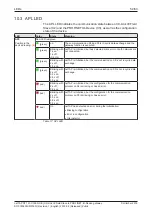
10.5 LEDs CC-Link IE Field-Slave
The subsequent table describes the meaning of the CC-Link IE Field-Slave
LEDs.
LED
Color
State
Meaning
RUN
Position in the device
drawing:
(1)
LED green
: Indicates the operation status
(green)
On
Operating normally (depending on "BusOn" status of the netX
firmware)
(off)
Off
A watchdog timer error or a hardware failure has occurred
ERR
Position in the device
drawing:
(2)
LED red
: Indicates the CP520 error status
(red)
On
Error in own station
(off)
Off
Normal operation
RD/SD
Position in the device
drawing:
(3)
LED orange
: Displays the reception and the sending status of the data
(orange)
On
Receive or send data
(off)
Off
No data received or sent
D-LINK
Position in the device
drawing:
(4)
LED yellow
: Indicates the status of the data link
(yellow)
On
Data link in operation (cyclic transmission in progress)
(yellow)
Blinking
Data link in operation (cyclic transmission stopped)
(off)
Off
Data link not performed (disconnected)
LINK
Position in the device
drawing:
CH0:
(12)
CH1:
(15)
LED green
(green)
On
Link up
(off)
Off
Link down
L-ERR
Position in the device
drawing:
CH0:
(13)
CH1:
(16)
LED yellow
(yellow)
On
Abnormal data received or loopback in progress
(off)
Off
Normal data received or loopback not performed
Table 20: LED states of the CC-Link IE Field Slave protocol
netTAP NT 151-CCIES-RE | CC-Link IE Field Slave to PROFINET IO-Device gateway
DOC180403UM01EN | Revision 1 | English | 2018-08 | Released | Public
© Hilscher 2018


