LEDs
13/258
5.2
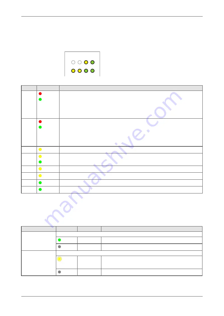
Gateway status LEDs
LEDs indicating communication status, system status, application status
and voltage supply. The position of the LEDs is indicated by position
(3)
in
section
Positions of the LEDs on the gateway
ERR
NS
RUN
MS
APL
SYS
LED1 LED2 ACT POW
Figure 4: Gateway state LEDs
LED
Color
Meaning
ERR
NS
(red)/
(green)
LED communication status Real-Time-Ethernet.
Name and function depends on used RTE protocol:
PROFINET IO Device =
ERR
(Bus failure)
EtherNet/IP Adapter =
NS
(Network status) See section
LEDs of the PROFINET IO Device interface
page 14] and section
RUN
MS
(red)/
(green)
LED communication status Real-Time-Ethernet.
Name and function depends on used RTE protocol:
PROFINET IO Device =
RUN
(System failure)
EtherNet/IP Adapter =
MS
(Module status)
LEDs of the PROFINET IO Device interface
page 14] and section
APL
( yellow)
Application status
SYS
(yellow)/
(green)
System status
LED1
( yellow)
GPIO12: can be programmed, currently not used.
LED2
(yellow)
GPIO13: can be programmed, currently not used.
ACT
(green)
Activity
POW
(green)
Voltage supply is OK
Table 4: Description of gateway status LEDs
5.3
LEDs of the LAN interface
LEDs indicating state of the LAN communication. For the positions of the
LAN LEDs, see section
Positions of the LEDs on the gateway
LED
Color
State
Meaning
LINK
Position in the device
drawing
(3)
LED green
(green)
On
100 MBit MBit network connection
(off)
off
10 MBit or no network connection
RX/TX
Position in the device
drawing
(2)
LED yellow
(yellow)
Flickering
(load
dependent)
The device sends/receives frames
(off)
off
The device does not send/receive frames.
Table 5: LEDs LAN interface
Edge Gateway | NIOT-E-TPI51-EN-RE (Connect)
DOC170502UM04EN | Revision 4 | English | 2018-08 | Released | Public
© Hilscher 2017 – 2018


