background image

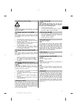
1. Press the on / off buttons on the PRI 36 rotating

laser and on the PRA 36 simultaneously and keep

them pressed for at least 3 seconds.

When pairing has been carried out successfully, a

signal tone is emitted by the PRA 36 and all LEDs

on the PRI 36 rotating laser blink.

At the same time, a chain symbol appears briefly

in the PRA 36 display. Both appliances switch off

automatically after pairing.

2. Switch on the paired tools.

The “paired” symbol appears in the display (see

“Troubleshooting” section).

7 Operation

7.1 Switching the tool on

Press the on / off button.

NOTE

After switching on, the tool begins to level itself automat-

ically.

7.2 Working with the PRA 36

The PRA 36 is a laser receiver (front) and, at the same

time, a remote control unit (rear). The remote control

makes working with the rotating laser more convenient

and is required in order to make use of certain functions.

7.2.1 Working with the laser receiver as a hand-

held unit

1. Press the on / off button.

2. Hold the PRA 36 in the plane of the rotating laser

beam.

The laser beam is indicated by visual and audible

signals.

7.2.2 Using the PRA 36 in the PRA 80 receiver

holder

12

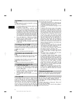
1. Open the catch on the PRA 80.

2. Place the PRA 36 in the PRA 80 receiver holder.

3. Close the catch on the PRA 80.

4. Switch the laser receiver on by pressing the on / off

button.

5. Turn the rotating grip to the open position.

6. Secure the PRA 80 receiver holder on the telescopic

staff by tightening the clamping knob.

7. Hold the PRA 36 with the receiving window in the

plane of the rotating laser beam.

The laser beam is indicated by visual and audible

signals.

7.2.3 Working with the PRA 81 height transfer

device

13

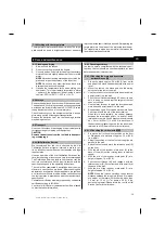
1. Open the catch on the PRA 81.

2. Insert the PRA 36 in the PRA 81 height transfer

device.

3. Close the catch on the PRA 81.

4. Switch the PRA 36 on by pressing the on / off button.

5. Hold the PRA 36 with the receiving window in the

plane of the rotating laser beam.

6. Position the PRA 36 so that the distance display

shows “0”.

7. Use the measuring tape to measure the desired

distance.

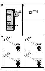
7.2.4 Menu options

3 4

Press the on / off button for two seconds when switching

the PRA 36 on.

The menu then appears in the display.

Use the “Measuring units” button to select metric or

imperial measuring units.

Use the volume button to assign the more rapid signal

tone to the upper or lower area of the receiving window.

To access the extended menu, press the “Button lock”

button on the rear of the PRA 36. Use the direction

buttons (left/right) to make further selections from the

menu: e.g. adjust PRI 36 shock sensitivity, cancel pairing

or switch off wireless operation.

Settings that affect the PRI 36 become effective only

when the PRI 36 is switched on and in wireless contact.

The direction buttons (up/down) are used to change

the settings. Each setting then becomes effective and

remains effective the next time the tool is switched on.

To save the settings, switch the PRA 36 off.

7.2.5 Setting the measuring unit

The “Units” button can be used to set the desired unit,

corresponding to the country-specific version (mm / cm

/ in / ft / off).

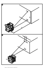
7.2.6 Setting the volume of the signal tone

3

The tool is set to “Normal” volume when switched on.

The volume can be adjusted by pressing the “Signal tone”

button. One of the following 4 settings can be selected:

“Low”, “Normal”, “High” or “Off”.

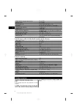
7.2.7 Button lock and double click

4 5

The button lock function of the PRA 36 prevents uninten-

tional entries being made and is indicated at the upper

left edge of the display on both sides of the PRA 36. The

lock symbol is either open (unlocked) or closed (locked).

Both sides of the remote control / laser receiver cannot

be used at the same time . If one side of the remote

control / laser receiver is in use, the other side is disabled

en

10

Printed: 14.04.2014 | Doc-Nr: PUB / 5162040 / 000 / 01

Summary of Contents for PRI 36

Page 1: ...PRI 36 Operating instructions en Mode d emploi fr Manual de instrucciones es Printed 14 04 2014 Doc Nr PUB 5162040 000 01...

Page 2: ...1 Printed 14 04 2014 Doc Nr PUB 5162040 000 01...

Page 3: ...2 3 4 5 Printed 14 04 2014 Doc Nr PUB 5162040 000 01...

Page 4: ...6 7 8 9 10 11 Printed 14 04 2014 Doc Nr PUB 5162040 000 01...

Page 5: ...12 14 13 Printed 14 04 2014 Doc Nr PUB 5162040 000 01...

Page 6: ...35 15 D F E G 17 16 Printed 14 04 2014 Doc Nr PUB 5162040 000 01...

Page 7: ...18 5 19 5 Printed 14 04 2014 Doc Nr PUB 5162040 000 01...

Page 8: ...designation remote control laser receiver always refers to the Hilti PRA 36 Rotating laser 1 Laser beam plane of rotation Rotating head Grip Control panel Battery Battery compartment Base plate with...

Page 9: ...t power under the above conditions is 4 5 mW Location of identification data on the tool The type designation and serial number can be found on the type identification plate on the tool Make a note of...

Page 10: ...e user to determine the exact position of the receiver relative to the laser plane with millimeter accuracy in a single operation 2 6 Speed of rotation line function 3 speeds of rotation are available...

Page 11: ...l or is exhibiting some other error 2 13 Charge status of the Li ion battery during operation LEDs light constantly LEDs blink Charge status C LED 1 2 3 4 C 75 LED 1 2 3 50 C 75 LED 1 2 25 C 50 LED 1...

Page 12: ...mW IEC 60825 1 EN 60825 1 2007 Class IIIa visible 532 nm 4 5 mW CFR 21 1040 FDA Speed of rotation 300 450 600 min Slope range 8 6 5 per axis Self leveling range 5 Power source 7 2V 6Ah Li ion battery...

Page 13: ...dry 25 60 C 13 140 F Charging temperature 0 40 C 32 104 F Weight 0 23 kg 0 51 lb Dimensions L x W x H 110 mm 4 33 x 50 mm 1 97 x 32 mm 1 26 PRA 84 G Li Ion battery Rated voltage normal mode 7 2 V Max...

Page 14: ...n or dampness q Check the tool before using it for important mea suring work r Check the accuracy of the measurements several times during use of the tool s Use the AC adapter only for connecting to t...

Page 15: ...rful electromagnetic radiation leading to incorrect operation Check the accuracy of the tool by taking measurements by other means when working under such conditions or if you are unsure Likewise Hilt...

Page 16: ...that have reached the end of their life must be disposed of safely and correctly to avoid environmental pollution 6 4 Fitting the battery 6 CAUTION Before inserting the battery in the tool check to en...

Page 17: ...PRA 36 on by pressing the on off button 5 Hold the PRA 36 with the receiving window in the plane of the rotating laser beam 6 Position the PRA 36 so that the distance display shows 0 7 Use the measur...

Page 18: ...just the tool so that its vertical axis is positioned in the required direction 3 In order to ensure that the tool s specified accuracy can be maintained make sure that it is set up on a level surface...

Page 19: ...is being monitored 1 Preparation for activation of the surveillance function is basically the same as the procedure for activation of automatic alignment mode see 7 5 2 2 Position the tool at the desi...

Page 20: ...te provide written verification that the tool operates in accordance with the manufacturer s specification Calibration certificates are always required by companies certified according to ISO 900x You...

Page 21: ...mode for max 4 h and then switches itself off Activate the tool by pressing the Sleep button Activate the tool settings after activating the tool The display shows this symbol Fault Contact Hilti Ser...

Page 22: ...ticular installation If this equipment does cause harmful interference to radio or television recep tion which can be determined by turning the equipment off and on the user is encouraged to try to co...

Page 23: ...on T te rotative Poign e Panneau de commande Bloc accu Compartiment accu Semelle avec filetage 5 8 DEL Affichage de l tat de charge des piles Verrouillage Prise de charge Panneau de commande du laser...

Page 24: ...t danger g n ral Avertisse ment mati res corrosives Avertisse ment tension lectrique dangereuse Uniquement destin une utilisation l int rieur Recyclage des mat riaux Rayonne ment laser viter tout rayo...

Page 25: ...uement apr s la mise en marche de l appareil Le faisceau laser est mis en marche uniquement lorsque la pr cision sp cifi e est atteinte Les DEL indiquent l tat de fonctionnement actuel de l appareil L...

Page 26: ...automatique vert La DEL verte clignote L appareil est en phase de mise ni veau La DEL verte est allum e en continu L appareil est mis niveau fonctionne correctement DEL d avertissement de choc orange...

Page 27: ...961 PA 962 4 Caract ristiques techniques Sous r serve de modifications techniques PRI 36 Port e r ception diam tre PRI 36 Avec PRA 36 2 300 m 6 56 984 25 ft Port e de la commande distance diam tre Ave...

Page 28: ...ervice 20 50 C 4 122 F Temp rature de stockage 25 60 C 13 140 F Classe de protection IP 56 conform ment IEC 60529 hormis le comparti ment des piles Adaptateur secteur PUA 81 pour blocs accus PSA 81 PR...

Page 29: ...rature ambiante avant de l utiliser k Prendre soin des outils lectroportatifs V rifier que les parties en mouvement fonctionnent cor rectement et qu elles ne sont pas coinc es V rifier galement qu auc...

Page 30: ...s accus que dans des char geurs recommand s par le fabricant Un chargeur appropri un type sp cifique de bloc accu peut engendrer un risque d incendie lorsqu il est utilis avec d autres blocs accus 5 3...

Page 31: ...reil est indiqu sur l appareil par les t moins du bloc accu pendant le processus de charge 6 2 2 Charge du bloc accu hors de l appareil 8 REMARQUE Pour la charge veiller ce que la temp rature soit com...

Page 32: ...e Arr t et les maintenir enfonc es pendant 3 s au moins Un appariement r ussi est indiqu par un signal sonore pour le PRA 36 et par un clignotement de toutes les DEL sur le laser rotatif PRI 36 Un sym...

Page 33: ...as possible d utiliser simultan ment les deux c t s de la t l commande du r cepteur laser Si un c t de la t l commande du r cepteur laser est libre l autre c t est automatiquement verrouill Au besoin...

Page 34: ...uteur du plan horizontal de mise niveau puis rep rer l inclinaison des hauteurs La mise niveau de l appareil est seulement optimale si ces hauteurs sont identiques sur les deux points 7 6 1 Installati...

Page 35: ...lan de re p re Si le plan laser se d place hors de la fen tre du r cepteur laser ou que le contact visuel direct entre le laser rotatif et le r cepteur laser est entrav pendant une p riode prolong e 2...

Page 36: ...1 1 Contr le des axes principal et transversal horizontaux 17 1 Disposer le tr pied environ 20 m env 60ft du mur et orienter la t te du tr pied l horizontale l aide d un niveau bulle 2 Monter l appar...

Page 37: ...ppareil en appuyant sur la touche Veille Apr s activation acti ver les r glages de l appareil Symbole affich Interf rences Consulter le S A V Hilti 10 Recyclage AVERTISSEMENT En cas de recyclage incor...

Page 38: ...rantie dans des installations de type particulier Si cet appareil provoque des interf rences nuisibles la r ception radio ou t l vision ce qui peut tre constat en l arr tant et en le remettant en marc...

Page 39: ...zal rotatorio Empu adura Panel de control Bater a Compartimento para la bater a Placa base con rosca de 5 8 LED de indicaci n del estado de las pilas Bloqueo Hembrilla de carga Panel de control del l...

Page 40: ...ciones recogidas anteriormente la potencia de salida media es 4 5 mW Ubicaci n de los datos identificativos de la herra mienta La denominaci n del modelo y la identificaci n de serie se indican en la...

Page 41: ...rayo l ser a gran distancia 2 5 Medici n digital de la distancia El PRA 36 indica digitalmente la distancia entre la superficie de l ser y la muesca de marcado del PRA 36 De este modo en un paso de t...

Page 42: ...de indicaci n de inclinaci n naranja El LED naranja est encen dido de forma constante El modo de inclinaci n est activado Todos los LED Todos los LED parpadeando La herramienta ha recibido un golpe h...

Page 43: ...PRA 36 0 200 m 0 656 17 ft Precisi n 1 mm 0 04 por cada 10 m 33 ft a una temperatura de 25 C 77 F Rayo de plomada ngulo recto constante respecto a la superficie de rota ci n Clase de l ser PRI 36 Clas...

Page 44: ...timento para bater as Bloque de alimentaci n PUA 81 para bater a PSA 81 PRA 84 PRA 84 G y monitor PSA 100 Alimentaci n de corriente nominal 115 230 V Frecuencia de red 47 63 Hz Potencia de referencia...

Page 45: ...tar al funcionamiento de la herramienta En cargue la reparaci n de las piezas defectuosas antes de usar la herramienta Muchos accidentes son consecuencia de un mantenimiento inadecuado de la herramien...

Page 46: ...yo no est orientado hacia Ud u otras personas al colocar la herramienta b Durante el trabajo con los conductores procure no adoptar posturas forzadas Procure que la postura sea estable y mant ngase si...

Page 47: ...nde a la temperatura de carga recomendada de 0 a 40 C de 32 a 104 F 1 Retire la bater a de la herramienta e inserte el co nector del bloque de alimentaci n o el conector de bater a para autom vil 2 Du...

Page 48: ...i n de la herramienta Pulse la tecla Encendido Apagado INDICACI N Tras el encendido la herramienta comienza la nivelaci n autom tica 7 2 Procedimiento de trabajo con el PRA 36 El PRA 36 es al mismo ti...

Page 49: ...I N La velocidad de rotaci n puede modificarse accionando la tecla Velocidad de rotaci n situada en el panel de control del l ser rotatorio o en el PRA 36 Las velocidades de rotaci n posibles son 300...

Page 50: ...l ser rotatorio se encienda el modo de inclinaci n situado en la parte superior derecha 4 Una vez lograda la nivelaci n se conecta el rayo l ser y es posible inclinar el PRA 36 7 6 2 Ajuste manual de...

Page 51: ...trabajo 7 10 Procedimiento de trabajo con la diana La diana incrementa la visibilidad del rayo l ser La diana se utiliza especialmente en condiciones de luminosidad claras o en cualquier otro lugar en...

Page 52: ...arcarlos en la pared Si se ha procedido correctamente la distancia verti cal entre los puntos 1 y 3 marcados eje principal o los puntos 2 y 4 eje transversal deber a ser 5 mm en 20 m en 60 ft Si la di...

Page 53: ...iezas de pl stico se generan gases t xicos que pueden afectar a las personas Si las pilas est n da adas o se calientan en exceso pueden explotar y ocasionar intoxicaciones incendios causticaciones o c...

Page 54: ...ci n de ra dio o televisi n se puede comprobar desconectando y volviendo a conectar la herramienta el usuario de ber solventar estas anomal as aplicando las medidas siguientes Reoriente o cambie de lu...

Page 55: ...el 423 2342111 Fax 423 2342965 www hilti com Hilti registered trademark of Hilti Corp Schaan W 4210 0414 00 Pos 3 1 Printed in Germany 2014 Right of technical and programme changes reserved S E O 2044...

Reviews: