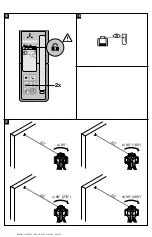
(locked) automatically. The enabled side can be changed
by double-clicking the lock symbol.
In order to avoid incorrect operation, the “Automatic
alignment”, “Surveillance” and “Special line” commands
must be confirmed by a double click. For the sake of
simplicity, this is not mentioned each time in further
sections of these operating instructions.
7.3 Basic functions of the PRI 36
The tool is designed to be used to determine, transfer
and check levels, verticals, slopes and right angles.
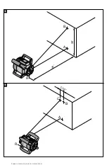
7.3.1 Setting the speed of rotation
2 4
NOTE
The speed of rotation can be adjusted by pressing the
“Speed of rotation” button (on the control panel of the
rotating laser or on the PRA 36). The speeds of rotation
are 300, 450 and 600 /min.
7.3.2 Selecting the line function
2 4
NOTE
When the “Line” button is pressed, the rotating laser
projects a line which can be lengthened or shortened by
further presses of the button.
NOTE
With the aid of the PRA 36 laser receiver it is also possible
to stop rotation of the laser and to project a line at the
position of the PRA 36. To do this, move the PRA 36 laser
receiver into the plane of the laser beam and press the
“Special line” button twice (double click).
7.3.3 Moving the laser line
The laser line can be moved to the left or right by pressing
the “Direction” buttons (PRI 36 or PRA 36). Holding down
the button results in continuous movement and increases
the speed of movement of the laser line.
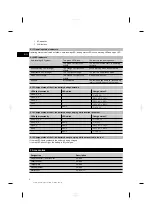
7.4 Working in the horizontal plane
3 4
1. Depending on the application, the rotating laser
may, for example, be mounted on a tripod or, alter-
natively, on a wall mount. The angle of inclination of
the surface on which it stands should not exceed ±
5°.
2. Press the on / off button.
3. The laser beam switches on and the head begins to
rotate at a speed of 300 /min as soon as the tool
has leveled itself.
7.5 Working in the vertical plane
14
1. When working in the vertical plane, place the tool
on its metal feet so that the control panel faces
upwards. Alternatively, the rotating laser may also be
mounted on a suitable tripod, wall bracket, facade
adapter or batter board adapter.
2. Adjust the tool so that its vertical axis is positioned
in the required direction.
3. In order to ensure that the tool’s specified accuracy
can be maintained, make sure that it is set up on
a level surface or mounted sufficiently level on the
tripod or other accessory.
4. Press the on / off button.
After the tool has leveled itself automatically, it
projects a stationary laser beam vertically down-
wards. This projected point is the reference point
and is used to position the tool.
5. The speed of rotation can be adjusted by pressing
the “Speed of rotation” button (on the control panel
of the rotating laser or on the PRA 36).
7.5.1 Manual alignment
Manual alignment of the vertical plane is carried out by
pressing the direction buttons (up/down) on the rear of
the PRA 36.
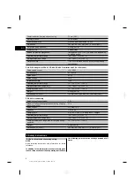
7.5.2 Auto-alignment
15
Hold the PRA 36 at the point to be aligned, with the
receiving side facing the PRI 36, and then press the
“Automatic alignment” button twice in quick succession.
NOTE
Check to ensure that the receiving side of the receiver
is not disabled (locked). Double-click the lock symbol to
unlock the side of the receiver.
The laser plane alignment procedure then begins. Short
signal tones are emitted while this is taking place.
The direction of the search can be changed by pressing
the “Automatic alignment” button.
The alignment procedure can be canceled by a double
click.
As soon as the laser beam strikes the receiving window
of the PRA 36, the beam moves to the position of the
marking notch (reference plane).
A continuous signal tone is emitted, indicating the end
of the procedure, as soon as the laser beam finds the
position of the marking notch.
If the automatic alignment process was not successful
(takes more than 2 min.), short signals sound and the
automatic alignment symbol goes out. This indicates that
the automatic alignment process was aborted.
7.6 Working with slopes
NOTE
For optimum results, check that the PRI 36 is correctly
aligned. The best way to do this is by selecting 2 points
on the left and right of the tool, each at 5 m (16.4 ft), but
parallel to the tool axis. Mark the height of the horizontal
plane and then, after setting the slope, mark the heights.
The tool is aligned optimally only when these heights are
identical at both points.
en
11
Printed: 14.04.2014 | Doc-Nr: PUB / 5162040 / 000 / 01
Summary of Contents for PRI 36
Page 2: ...1 Printed 14 04 2014 Doc Nr PUB 5162040 000 01...
Page 3: ...2 3 4 5 Printed 14 04 2014 Doc Nr PUB 5162040 000 01...
Page 4: ...6 7 8 9 10 11 Printed 14 04 2014 Doc Nr PUB 5162040 000 01...
Page 5: ...12 14 13 Printed 14 04 2014 Doc Nr PUB 5162040 000 01...
Page 6: ...35 15 D F E G 17 16 Printed 14 04 2014 Doc Nr PUB 5162040 000 01...
Page 7: ...18 5 19 5 Printed 14 04 2014 Doc Nr PUB 5162040 000 01...


