3.2.11
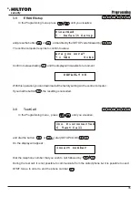
IR on delayed zone
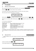
This option enables the infrared detector that is on the panel in order to alarm the zone 1 (delayed):
Select:
In order to change the status, press the button or .
NOTE: In both cases, when the sensor detects a presence in the surroundings of the central computer,
the display backlights and keyboard backlights turn on.
D i s a b l e d
E n a b l e d
3.2.12
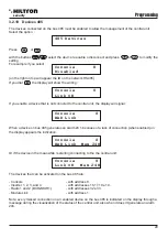
Partial System A and B
This option allows to set the zones to include/exclude from supervision when you enable the central
computer in a partial manner.
Using the buttons , to scroll the menu SETUP until the word:
or:
On the second line of the display, appear the numbers of the zones that will be guarded with the enabled
system set as needed. Dial the number of the zones you want to modify.
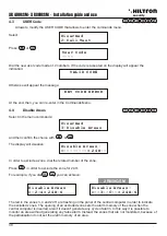
P a r t i a l A
> 1 2 - - <
P a r t i a l B
> - - 3 4 <
3.2.10
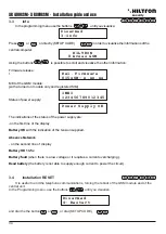
Logical zones / balanced / radio
This option allows you to change the functioning of the entrances of the zones and to signal the radio zones.
Select this option from the SETUP menu with the buttons
In order to change the setting related to the zones, dial the number corresponding to the zone to modify
one time to pass from logical to balanced, then from balanced to radio and finally to come back from radio
to logical.
(with the button you can modify the line 24h, only LOCIGAL or BALANCED).
A balanced zone requires to close the line through a resistance of 3,3 Kohm.
The central computer will recognize the alarm on the zone both when increases the impedance of the line
(the opening of the line or the cutting of the conductors), both when decreases (short circuit of the line). A
logic zone, instead, doesn't need resistances and it will be considered not in alarm when the line is closed.
The balanced line provides a better degree of safety towards possible manumissions. If a criminal puts in
short circuit the two conductors of a logic line connected to a sensor, the same sensor won't start the
alarm of the central computer. With a balanced line, instead, the manumission and the attempt to put it in
short circuit, will allow the signal of alarm to start on the central computer. To make an effective protection
of the line, the balancing resistance that is inserted on the line in series, it must be placed as nearest as
possible to the end of the line, next to or inside the sensor and far from the central computer. A zone
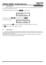
configured as radio zone, will accept the sensor signals of the serie XR on which is set the code of the
following table and also the radio code of the central computer.
NOTE: When a zone is defined “Radio” the relative input in the terminal board is not used.
9
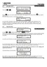
A r e a s L o g / B a l / R f
> L L L L < 2 4 H : L
A r e a s L o g / B a l / R f
> L B B L < 2 4 H : B
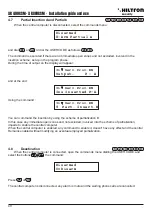
A r e a s L o g / B a l / R f
> L L L L L L L L < 2 4 H : L
A r e a s L o g / B a l / R f
> L B B L L B L R R < 2 4 H : B
000 = zone1
100 = zone2
010 = zone3
001 = zone5
001 = zone5
110 = zone4
101 = zone6
101 = zone6
011 = zone7
011 = zone7
111 = zone8
111 = zone8
XR800GSM
XR800GSM
XR800GSM
Programming
security
security
24
25
XR400GSM
- XR
800GSM - Installation guide and use
I R O n A r e a 1
I R O n A r e a 1


