Concept for HIQuad X
System
Page 24 of 110
HI 803 211 E Rev. 1.01.00
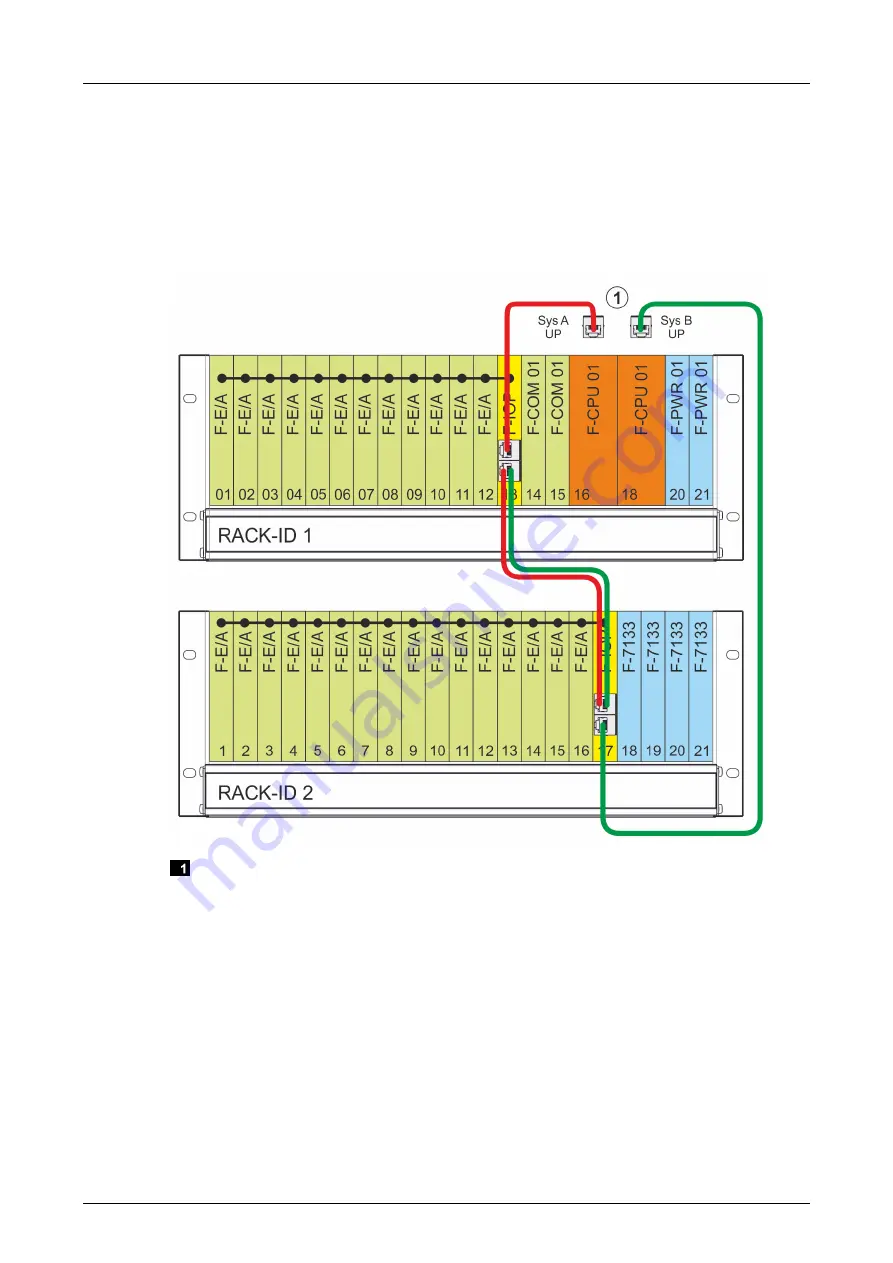
Figure 10 shows the example of an H41X redundancy system with system buses A and B. An
additional extension rack can be connected to the system buses. The extension rack is
connected to the H41X base rack via the I/O processing module and the system buses A and B,
see F-IOP 01 manual (HI 803 219 E).
The advantage of a redundancy system is that, if one system bus is disconnected, the system
can continue to operate via the redundant system bus. If one I/O processing module fails, the
I/O modules in the affected rack enter the safe state while the other rack is not impaired by this
failure.
System bus interfaces on the rear side of the base rack
Figure 10: Example of H41X Redundancy System
The rack IDs for the HIQuad H41X system are fixed.
To ensure a clearer overview, HIMA recommends the following:
Between Sys A UP and the F-IOP module, use red patch cables for system bus A.
Between Sys B UP and the F-IOP module, use green patch cables for system bus B.
Summary of Contents for HIQuad H41X
Page 1: ...Manual HIQuad X System Manual...
Page 109: ......


