System
Product Description
HI 803 211 E Rev. 1.01.00
Page 31 of 110
4.2.1
H51X Backplane
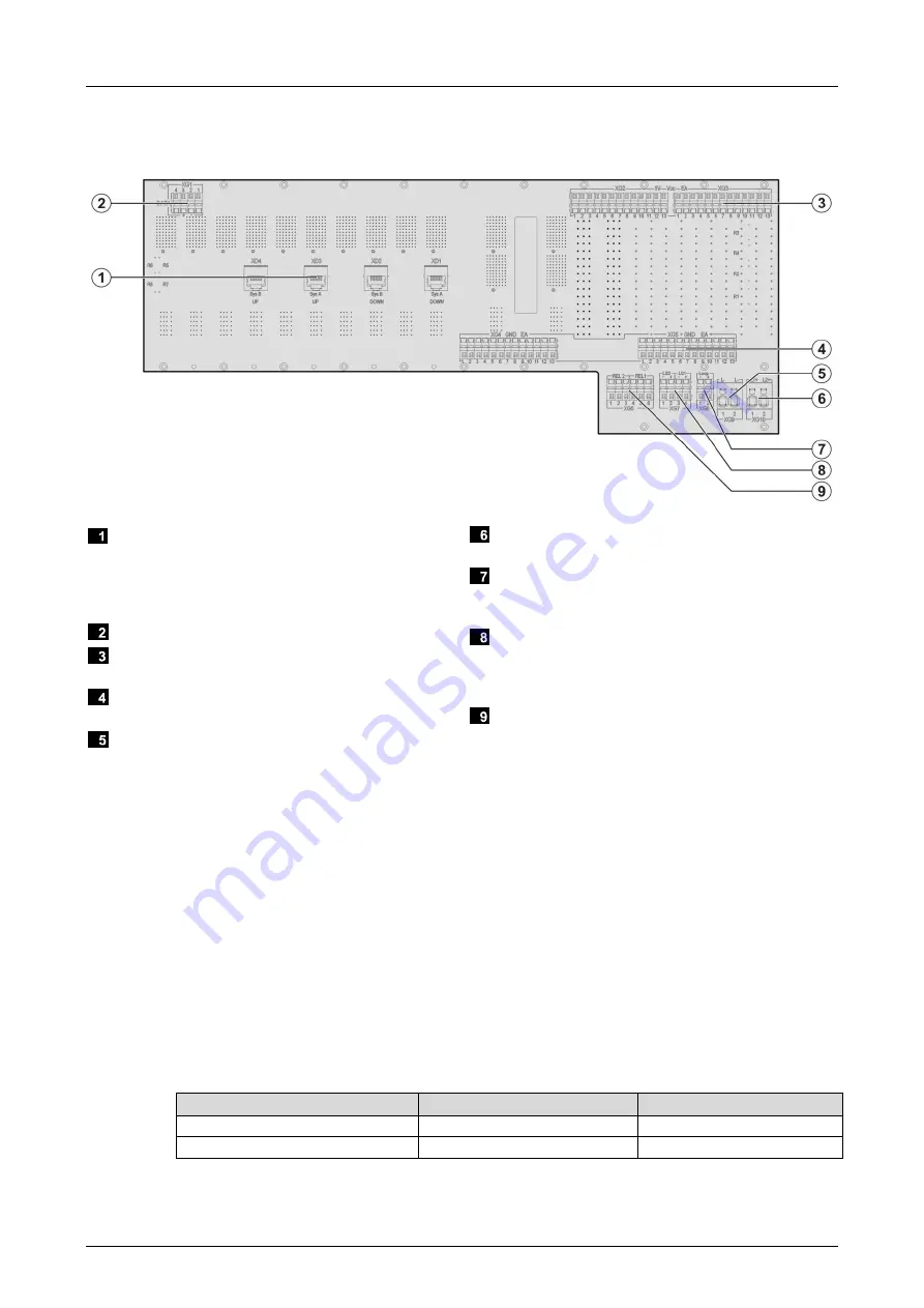
The following figure shows the rear side of the H51X backplane:
System bus connections
Sys. A DOWN (XD1)
Sys. B DOWN (XD2)
Sys. A UP (XD3)
Sys. B UP (XD4)
XG1 (DATA) Not applicable (for future use)!
5 V power supplies for extension racks, XG2
and XG3
Reference potential (GND) for extension racks,
XG4 and XG5
Connection to L- reference potential (24 V
supply), XG9
Clamp terminal block for redundant 24 V power
supply, XG10
Control cabinet diagnostics for future
applications, XG8 (loop) Not applicable (for
future use)
24 V power supply (LS1, LS2) for the F-IOP 01
modules in the extension racks, XG7 (buffer
module in slot 6 supplies LS1 and buffer module
in slot 7 supplies LS2)
Signaling relay contacts for F-PWR 02, XG6
Figure 15: Rear View of H51X Backplane
4.2.1.1
Supply of the H51X Base Rack
For supply and power distribution, HIMA recommends using the following components:
K 7205: Redundant supply up to a maximum of 63 A total current with fuse protection of up
to 18 individual circuits with circuit breakers.
K 7212: Redundant supply up to a maximum of 35 A total current with 2 decoupling diodes
and 2 mains filters, with fuse protection of up to 12 individual circuits with circuit breakers.
K 7213: Redundant supply up to a maximum of 35 A total current with fuse protection of up
to 12 individual circuits with circuit breakers.
K 7214: Redundant supply up to a maximum of 150 A total current with fuse protection of up
to 18 individual circuits with circuit breakers.
The 24 V power supply is connected to the following terminals:
Spring terminal
Cross-section and color
Fuse
XG10.1/.2 (L1+, L2+)
2.5 mm² RD
Maximum 16 A gL
XG9.1/.2 (L-)
2.5 mm² BK
Table 7:
Connection to the 24 V Power Supply
Summary of Contents for HIQuad H41X
Page 1: ...Manual HIQuad X System Manual...
Page 109: ......


