S. Himmelstein and Company
Strain Gage Reaction Torquemeters Installation Guide
© 2017 S. Himmelstein and Company—all rights reserved www.himmelstein.com
4
setup like this, reaction torque measurements will be in error to
the extent they, and extraneous load torques, exist. The accelera-
tion error component disappears during constant speed conditions
but, the windage error and extraneous load components are always
present. Only in-line torque measurements are immune to these
error sources. When angular motion is limited and test cycle rates
are low enough to permit “cable windup” without wire fatigue,
reaction sensors are an economic torque measurement solution; see
Figure 4.
A.2 Installation Discussion
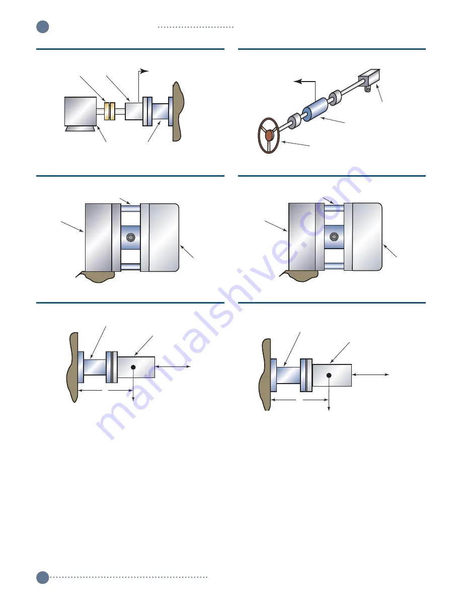
To measure reaction torque, one end of the sensor must be
mechanically grounded. The ground may be direct, as in
Figures 1, 2 and 3,
or, it can be through the Load or Driver as in
Figures 5 and 6.
As noted on those figures, the sensor is installed
on the device whose torque is to be measured and the ground is
made via the other device.
A.3 Extraneous Loads
Any force or moment sensor input, other than the reaction torque
is an extraneous load. Depending on the installation, see
Figures
7 and 8
, these could include bending moments and axial thrust
(tension or compression). The Bulletin describing your torqueme-
ter lists the maximum safe extraneous loads that can be applied,
Coupling
Pump
Motor
Reaction
Torquemeter
To Hyd. Load
Figure 3. Measuring Absorber Torque
Drive Motor
Torquemeter
Load Device
Figure 5. C-Face Torquemeter Measures Load Torque
Torquemeter
Test Item
F
d
W
Figure 7. Extraneous Load Definition for Flanged Sensor
Torquemeter
Test Item
F
d
W
Figure 8. Extraneous Load Definition for Shaft Sensor
Steering Wheel
To Amplifier
Steering Gear
Reaction
Torquemeter
Figure 4. Reaction Torquemeter Senses Rotating Torque
Load Device
Torquemeter
Test Motor
Figure 6. C-Face Torquemeter Measures Motor torque


