background image

Operators’ Safety Summary 


PEM 100 User Manual 

AC Power Source 

This product is intended to operate from an AC power source in the 100-240 VAC 
range, 50-60 Hz, line to neutral.  A protective ground connection by way of the 
grounding connector in the power cord is essential for safe operation.  Power line 
requirements are listed in the specifications section and on the rear panel of the 
instrument. 

The power cord provided with this instrument is less than 3 meters in length.  
Use only the power cord and connector specified for your product to work with your 
local power outlets.   Use only a power cord that is in good condition.   

The appliance inlet or plug on cord should always be positioned to be accessible by 
the operator.  To disconnect all power from the instrument, pull the power cord from 
the wall outlet or from the appliance inlet. 

Do Not Operate Without Cover 

To avoid personal injury, do not operate the PEM-100 Controller without the cover. 

Ensure the controller ventilation openings located on the top and bottom of the 
enclosure are clear of any obstructions. 

Summary of Contents for PEM-100

Page 1: ...PEM 100 PHOTOELASTIC MODULATOR USER MANUAL Hinds Instruments Inc P N 010 0000 021 UM Rev H ...

Page 2: ...ished by Hinds Instruments Inc is believed to be accurate and reliable however no responsibility is assumed by Hinds Instruments Inc for its use nor for any infringements of patents or other rights of third parties which may result from its use No license is granted by implication or otherwise under any patent rights of Hinds Instruments Inc In all respects the English version of this manual is co...

Page 3: ...CAUTION DO NOT turn on your modulator unless the optical head and the electronic head are connected by the head to head interconnect cable SERIOUS DAMAGE MAY RESULT ...

Page 4: ......

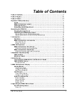
Page 5: ...100 Controller 13 PEM 100 Controller Front Panel 13 PEM 100 Controller Front Panel Buttons 14 PEM 100 Controller Rear Panel 15 PEM 100 Controller Rear Panel Connections 15 3 Modulator Head Assembly 17 Optical Head 17 Electronic Head 20 4 Initial Set Up 21 Connecting the PEM Optical and Electronic Heads 21 Optical Bench Set up 25 Functional Check 25 5 PEM 100 Controller Display 27 Display Modes 27 ...

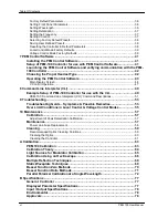
Page 6: ...r CLI 49 Example Setup of PEM 100 Controller for use with the CLI 49 PEM 100 Command Line Interpreter CLI Command Descriptions 51 9 Troubleshooting 53 Troubleshooting Guide Symptoms Possible Remedies 53 Over Limit Conditions in Local Control Voltage Control Modes 55 10 Maintenance 57 Calibration 57 Adjustment of Peak Retardation Calibration 57 Maintenance 57 Power Line Fuse Replacement 58 Cleaning...

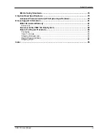
Page 7: ...anced Thermal Control ATC Option Specifications 79 D User Support Information 81 PEM 100 Limited Warranty 81 Exclusions 81 Overview of the PEM 100 Help System 82 Return For Repair Procedure 83 Packaging 83 Items To Include 83 Shipping Arrangements 83 Return Shipping Address 84 Shipping Costs 84 Index 85 ...

Page 8: ...Table Of Contents viii PEM 100 User Manual ...

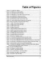
Page 9: ...Figure 3 3 Model II ZS50 Optical Head Dimensions 18 Figure 3 4 II FS84 Optical Head Dimensions 19 Figure 3 5 II ZS37 Optical Head Dimensions 19 Figure 3 6 Electronic Head Dimensions 20 Figure 4 1 Connecting I FS50 Optical Head to Electronic Head 22 Figure 4 2 Connecting II ZS50 Optical Head to Electronic Head 22 Figure 4 3 Connecting II ZS50 Optical Head to Electronic Head Cross Connection 23 Figu...

Page 10: ...roperly Inserted In Fuse Holder 59 Figure 10 3 Direction of cotton swab wiping motion 60 Figure 10 4 Junction between Optical Element and Transducer 61 Figure A 1 Typical Optical Setup 64 Figure A 2 Oscilloscope Calibration Method 66 Figure A 3 Waveform for Half wave Retardation 67 Figure A 4 Retardation 90 of Half wave 67 Figure A 5 Retardation 110 of Half wave 68 Figure A 6 Waveform for a Retard...

Page 11: ...le 6 2 Voltage Control Mode Factory Defaults 39 Table 8 1 CLI Port Settings ASCII Setup 49 Table 8 2a PEM 100 Command Line Interpreter Command Descriptions 51 Table 8 2b PEM 100 Command Line Interpreter Command Descriptions 52 Table 9 1a Troubleshooting Guide Symptoms Possible Remedies 53 Table 9 1b Troubleshooting Guide Symptoms Possible Remedies 54 Table D 1 Contacting Technical Support 82 ...

Page 12: ...Table of Tables xii PEM 100 User Manual ...

Page 13: ...s or practices that could result in personal injury or loss of life CAUTION statements identify conditions or practices that could result in damage to the equipment or other property NOTICE statements identify conditions or practices that are important in proper use of the equipment to get the expected results PEM 100 Controller Labels The serial number and CE certification labels are located at t...

Page 14: ...strument is less than 3 meters in length Use only the power cord and connector specified for your product to work with your local power outlets Use only a power cord that is in good condition The appliance inlet or plug on cord should always be positioned to be accessible by the operator To disconnect all power from the instrument pull the power cord from the wall outlet or from the appliance inle...

Page 15: ...ide note the location and the condition of the shock watch If the shipment receives handling rough enough to trigger the shock watch the watch will turn red 3 Open the container and inspect the contents Do not throw away the container or any damaged parts Try to keep all items in the same condition as originally received 4 Notify the Transport Company immediately in writing preferably by facsimile...

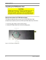
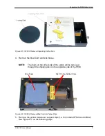
Page 16: ...done the PEM system will not operate and the optical head may be irreversibly damaged Special Instructions for I FS50 Optical Head The following unpacking instructions are for an I FS50 PEM optical head All optical head models except for the II FS42 and II IS42 follow these instructions 1 Ensure the work surface is clean and free of dust 2 Using a 1 Phillips screw driver remove the shipping disk F...

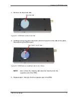
Page 17: ... 4 Carefully remove the inner blue foam and lens tissue from this side of the optics thus exposing the PEM optics Inner Foam Lens Tissue Figure S 3 I FS50 Remove Inner Blue Foam Lens Tissue NOTE Also remove the shipping disk and inner blue foam on the opposite side of the PEM 5 Repeat steps 1 through 4 for the opposite side of the PEM ...

Page 18: ...e zip lock bag provided in the event that the PEM is returned to Hinds The shipper assumes all freight damage risk if the optical head is not packaged as supplied Special Instructions for II FS42 II IS42 Optical Head The following unpacking instructions are for an II FS42 and II IS42 PEM optical heads Unpacking other optical head designs may vary slightly 1 Ensure the work surface is clean and fre...

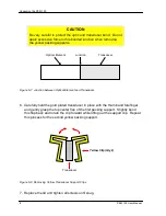
Page 19: ...ens tissue NOTE The foam on the other side of the optics will be removed through the shipping disk on the opposite side of the PEM Blue Foam Qty 2 Yellow Rubber Clips Figure S 6 II FS42 Remove Blue Foam Yellow Clips 5 Remove the yellow transducer support clips i e for models II FS42 and II IS42 See Figure S 7 on the following page ...

Page 20: ...een Optical Element and Transducer 6 Carefully hold the gold plated transducer in place with the thumb and forefinger and gently grasp the top center flap of the first packing support Slightly bend this flap back and rotate the clip forward while lifting out the support clip Repeat this process for the second yellow packing support Transducer Yellow Clip Qty 2 Figure S 8 Removing Yellow Transducer...

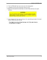
Page 21: ...ust particles on the optic surfaces CAUTION Use only oil free air when blowing lint or dust particles from the optic surfaces If using canned air hold the container upright or liquid will spray onto the optic surface 11 Save shipping disk foam and lens tissue in the zip lock bag provided in the event that the PEM is returned to Hinds The shipper assumes all freight damage risk if the optical head ...

Page 22: ...Unpacking the PEM 100 10 PEM 100 User Manual ...

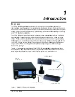
Page 23: ...ce proportional to the resulting strain Photoelastic modulators are resonant devices each producing oscillating birefringence at a fixed frequency in the low frequency ultrasound range 20 kHz to 100 kHz These factors result in a number of very useful advantages which are unique to the PEM including wide acceptance angle large aperture and high modulation purity Figure 1 1 provides an overview of t...

Page 24: ...ccessories Rack Mounting Kit The PEM 100 Controller can be mounted in a Hinds Instruments rack mount kit PN 023 0000 184 RS232 Converters Two RS232 converters are available RS232 to IEEE 488 Converter Hinds PN 020 2404 001 RS232 to USB Converter Hinds PN 036 9003 120 ...

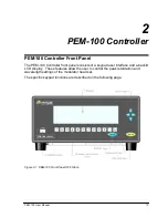
Page 25: ...ler front panel consists of a keypad user interface and a backlit LCD display These features allow the user to control the peak retardation and wavelength settings of the modulator head set The specific keypad functions are described on the following page Figure 2 1 PEM 100 Front Panel OFF State ...

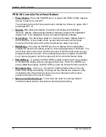
Page 26: ...splay field is highlighted enables the process for editing values or choosing parameters in that field The arrow keys and numeric keys can then be used to edit the field value or move between parameter choices When editing choosing is complete the ENTER key is pressed again to store the value and shift out of edit choose mode ESCAPE Key In general the ESCAPE key allows backing out of any display t...

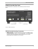
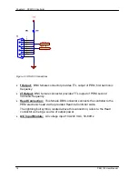
Page 27: ...rear panel Figure 2 2 PEM 100 Rear Panel PEM 100 Controller Rear Panel Connections RS232 Connection The RS232 Serial Port connector is a male DB9 and the connections are given in figure 2 3 on the following page This interface allows computer control of the modulator as well as monitoring of all controller operating parameters displayed on the front panel ...

Page 28: ...c frequency 2f Output BNC female connector provides TTL output of PEM second harmonic frequency Head Connection This female DB9 connector connects the controller to the PEM electronic head via the provided Head to Controller cable The lightning bolt symbol located above this connection refers to the Head connector as being a source of output power A C Input Module AC voltage input 100 240 VAC 50 6...

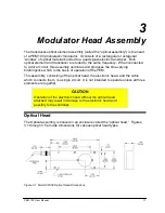
Page 29: ...s the time varying birefringence which is the basis of operation of the PEM This assembly consisting of the optical head the electronic head and the cable which connects them is a single circuit It is not intended to operate unless all three elements are together CAUTION Operation of the electronic head without the optical head attached may result in damage to the electronic head and possibly to t...

Page 30: ...Chapter 3 Modulator Head Assembly 18 PEM 100 User Manual Figure 3 2 Model II FS42 Optical Head Dimensions Figure 3 3 Model II ZS50 Optical Head Dimensions ...

Page 31: ...Optical Head PEM 100 User Manual 19 Figure 3 4 II FS84 Optical Head Dimensions Figure 3 5 II ZS37 Optical Head Dimensions ...

Page 32: ...ngle unit CAUTION Operation of the electronic head without the head to head cable and optical head connected should never be attempted Such operation will almost certainly result in damage to the electronic head Electronic Head The electronic head driver circuit consists of an active LC tank circuit connected in parallel to the optical head The head to head interconnect cable contributes capacitan...

Page 33: ...epending upon your specific application your head set may come with one of the following head to head interconnect cable s Single blue triaxial head to head interconnect cable Dual black coaxial head to head interconnect cables 1 Connect the optical head to the electronic head by means of the Head to Head interconnect cable See figures 4 1 and 4 2 on the following page CAUTION Operation of the mod...

Page 34: ...the blue triax Head to Head Interconnect cable provided Figure 4 1 Connecting I FS50 Optical Head to Electronic Head If there are dual standard BNC coax connectors on the optical and electronic heads connect the dual black coaxial Head to Head Interconnect cables provided Figure 4 2 Connecting II ZS50 Optical Head to Electronic Head ...

Page 35: ...ctronic head to the PEM 100 Controller using the Controller to Head cable 3 Connect the power cord to the PEM 100 Controller and plug it into an AC power source 4 Connect the RS232 serial interface cable to the computer if used for remote control 5 If the optical head came equipped with ATC Advanced Thermal Control then connect the power cord of the 24V DC power supply that came with the optical h...

Page 36: ...Chapter 4 Initial Set up 24 PEM 100 User Manual Figure 4 4 Connecting 1 FS50 Optical Head with ATC Option to Electronic Head ...

Page 37: ...ength selection device e g monochromator Monochromatic Light Source 45 Polarizer Modulator 0 Polarizer Controller Oscilloscope Reference 45 Detector Figure 4 5 Block Diagram for Oscilloscope Calibration Method The light source if unpolarized is followed by a polarizer at 45 degrees with respect to the horizontal the modulator with its axis horizontal 0 degrees a second polarizer often called the a...

Page 38: ...Polarizers and PEM 1f Reference Signal The detector circuitry deserves some special comment Care must be taken to ensure adequate frequency response typically several times the PEM operating frequency Pre amplified photo detectors are available from Hinds Instruments that fit this need See page 82 for contacting Hinds Instruments Inc ...

Page 39: ...elength and retardation for the PEM 100 Figure 5 1 Local Control Mode Display Wavelength WAV Displays the wavelength setting Wavelengths units can be set to display in nanometers nm micrometers µm and wavenumbers 1 cm To enter a different wavelength than what is displayed use the arrow keys to navigate to WAV and press ENTER Using the numeric buttons below the display or the arrow keys to the righ...

Page 40: ...different harmonic setting than what is displayed use the arrow keys to navigate to 1f and press ENTER Arrow to the desired harmonic setting and press ENTER To select a different frequency unit use the arrow keys to navigate to Hz and press ENTER Arrow to the desired frequency unit and press ENTER To save current Local Control Mode settings use the arrow keys to navigate to User Presets and press ...

Page 41: ... desired frequency unit and press ENTER To save current Voltage Control Mode settings use the arrow keys to navigate to User Presets and press ENTER The Save Current row heading is highlighted to signify the current settings are to be saved To save the current settings as a preset press ENTER then arrow to the numbered preset to save the current settings to and press ENTER to facilitate the save f...

Page 42: ...o allows the user to save current local control settings To access the User Presets menu from the Local Control Mode use the arrow keys to navigate to User Presets and press ENTER Figure 5 4 Local Control Mode User Presets Menu Save Current Select to save the current Control Mode settings Load Preset 1 Select to load Local Control Mode settings saved in Preset 1 Load Preset 2 Select to load Local ...

Page 43: ...ss the User Presets menu from the Voltage Control Mode use the arrow keys to navigate to User Presets and press ENTER Save Current Select to save the current Control Mode settings Load Preset 1 Select to load Voltage Control Mode settings saved in Preset 1 Load Preset 2 Select to load Voltage Control Mode settings saved in Preset 2 Load Preset 3 Select to load Voltage Control Mode settings saved i...

Page 44: ...m Configuration Menu Screen Settings To adjust the screen setting use the arrow keys to navigate to Screen Settings and press ENTER Use the arrow keys to select and adjust the Pixel or Screen brightness and press ENTER Press ESCAPE to return to the previous menu Restore Defaults To restore the factory default settings use the arrow keys to navigate to Restore Defaults and press ENTER Press ESCAPE ...

Page 45: ...ity Check None Flow Control None Table 5 1 PEM 100 Controller RS232 Settings System Info To view system information use the arrow keys to navigate to System Info and press ENTER Press ESCAPE to return to the previous menu Compare the software part number displayed with the chart below to see what head type the PEM 100 Controller was calibrated for Series System Info SW Suffix I FS 000 II FS IS 001...

Page 46: ...Chapter 5 PEM 100 Controller Display 34 PEM 100 User Manual ...

Page 47: ...turned ON by pushing the POWER button the controller is powered up with the factory default parameters When the controller is turned OFF the displayed parameters as well as newly loaded user presets are stored to memory When the controller is then turned back ON the controller is powered up with the parameters which were set when the controller was turned OFF ...

Page 48: ...dation Display of retardation units λ rad º Frequency harmonic 1f or 2f Frequency Units Hz kHz Voltage Control Mode VControl Frequency harmonic 1f or 2f Frequency Units Hz kHz Setting Wavelength For most experimenters the most useful units of retardation are phase units waves radians and degrees The controller requires the user to input the wavelength of light being used so that the proper electri...

Page 49: ... the Frequency The frequency shown is the harmonic frequency Frequency units may be set from within either the Local Control Mode or the Voltage Control Mode To set the controller to a different harmonic frequency 1 Arrow to 1f and press the ENTER button 2 Arrow to the desired harmonic 1f or 2f and press the ENTER button To set the controller to a different frequency unit 1 Arrow to kHz and press ...

Page 50: ...ned preset parameters Depending upon which control mode Local or Voltage is displayed the saved preset for the associated mode will be displayed To save user defined preset values 1 Arrow to User Presets and press the ENTER button 2 Press the ENTER button again to access the preset selection menu 3 Arrow to the desired preset label As Preset 1 As Preset 2 or As Preset 3 and press ENTER to save the...

Page 51: ...ller configuration for head type used Wavelength nm Retardation λ Current Settings Variable Variable Preset 1 543 5 nm 0 25 λ Preset 2 632 8 nm 0 125 λ Preset 3 1 54 µm 11 25 º Table 6 1 Local Control Mode Factory Defaults Voltage Control Mode Factory Defaults The Voltage Control Mode factory default settings for User Presets are below VCtrl Current Settings 0 999 Preset 1 1 111 Preset 2 2 222 Pre...

Page 52: ...Chapter 6 Operating the PEM 100 Controller 40 PEM 100 User Manual ...

Page 53: ... 1 Click on the dotnetfx exe file This installs the Micorsoft NET runtime version 1 1 onto the local computer 2 Errors encountered during the dotnefx exe file install may occur if the PC user does not have administrator privileges See your System Administrator for file installation assistance 3 Copy the PEMControl exe file to the desktop or a desired location on the local computer This is the file...

Page 54: ...tom of the software display and click the Update Frequency box A frequency number will be displayed next to the Frequency window if communication is occurring with the PEM 100 Controller NOTE Communication will not be successful if the wrong COM port number was selected The computer and software will hang up and both will need to be powered OFF or restarted Perform the above steps again to select ...

Page 55: ...Sys Config System Info menu and view the SW PN The XXX numbers of the 025 1000 XXX shown is the headset type 3 Click the Red X box to close the Advanced menu The headset type you selected should appear in the PEM Head Type box on the main PEM Control Software display Operating the PEM Control Software Screen displays and associated operational instructions of the PEM Control Software are captured ...

Page 56: ...hen launching the PEM Control Software the main display screen will appear with the default settings as shown This screen allows for adjustments to wavelength and retardation settings as well as provides selections for frequency and PEM head type Figure 7 2 Main Display Screen ...

Page 57: ...dingly Increment Wavelength The increment wavelength field displays the set number for wavelength increment adjustments Entering wavelength increments can be accomplished in 2 ways 1 Double click the incremental wavelength displayed to highlight the setting and then enter a new wavelength increment value 2 Click on the up or down arrow to the right of the increment wavelength display to adjust the...

Page 58: ...type field displays the last three digits shown in bold of the SW PN software part number 025 1000 XXX 000 which corresponds to the head set type and controller type Selecting the correct software part number can be accomplished in two ways 1 Click in the PEM Head Type display field The Advanced setting dialog box will appear See figure 7 2 Click on the PEM Head Type down arrow and select the corr...

Page 59: ... can be accomplished three ways 1 Double click the voltage displayed to highlight the setting and then enter a new voltage value 2 Click and hold the slider adjustment below the V Control display and drag the slider to the desired voltage setting 3 Click on the up or down arrow to the right of the V Control display to adjust the voltage setting by single digits Scan V Control The Scan V Control al...

Page 60: ... range defined by the starting and ending values by the number of steps selected 3 Enter the time delay between steps in the Delay between Steps field This time delay value is in milli Seconds so enter 1000 for a 1 second time delay between steps 4 Click the GO button to begin an automated V Control scan The V Control numerical display field will be updated for each new step in the scan ...

Page 61: ...minal program installed example Windows HyperTerminal 2 Connect a PEM headset to the PEM 100 Use the cable labeled PEM Controller to Head Cable for this purpose Also make sure the Electronic Head is connected to the Optical head using the cable or cables provided 3 Power on the PEM 100 Controller and set it to Remote Control mode 4 Power on the computer and open the terminal program Change the ter...

Page 62: ...5 Press the PC keypad Enter key which should result in an asterisk being displayed on the PC screen This indicates the terminal program is communicating with the PEM 100 6 Type the desired command from table 8 2 PEM 100 Control Line Interpreter Command Descriptions Example to set the PEM 100 retardation to wave type R 0250 then press Enter To read the retardation setting type R then press Enter ...

Page 63: ...lay if the 1F or 2F command is active Displays freq in 6 digits 039988 for example No change Correctly entered command followed by the currently selected frequency then a character on the next line Allow a few seconds for frequency stability I n n 0 or 1 Inhibit retardation 0 normal operation 1 inhibit None No change Correctly entered command followed by a character on the next line R nnnn nnnn 00...

Page 64: ...ngth Ret 632 8 nm 0 25 Displays PEM 100 SW PN 025 1000 XXX YYY XXX suffix is the software version YYY is the software revision No change Note that the present wavelength and retardation settings will change to the default settings after entering the Z command V n nnn and Vn nnn n nnn 0 000 to 4 850 Sets Vcntrl to n nnn None No change Correctly entered command followed by a character on the next li...

Page 65: ...let Blown power fuses on PEM 100 Controller see manual for instructions on replacing fuses Equipment incorrectly connected to back panel connectors Power OFF PEM 100 Controller and check connections per the instructions in this manual Modulation Problems Symptoms No frequency value is shown on the PEM 100 Controller or on the PEM Control software display See Figure 8 1 on following page Possible R...

Page 66: ...igure 8 1 below Possible Remedies Windows 2000 and 98 users will need to install the dotnetfx exe file from the CD onto PC Set the software COM port for the PC COM port used Click Update Frequency box on software display Restart the software if the COM port needs to be changed after clicking Update Frequency Ensure head set is connected to the PEM 100 Controller and the controller RS232 port conne...

Page 67: ... Mode the controller senses over limit conditions when retardation or wavelength settings are too high If this occurs the following message will be displayed Figure 9 2 Display Retardation Over Limit Message For Voltage Control Mode if the voltage input exceeds 4 85 volts an over limit message is displayed as follows Figure 9 3 Display Voltage Over Limit Message ...

Page 68: ...Chapter 9 Troubleshooting 56 PEM 100 User Manual ...

Page 69: ... as described in the Calibration appendix Even when other reference points are used this method should be regarded as the coarse adjustment on the modulator calibration The peak retardation calibration of the modulator is adjusted by R4 a multi turn trimpot labeled Range in the electronic head With the appropriate optical bench setup and detection system the trimpot is adjusted until the calibrati...

Page 70: ...es only with the type and value indicated Both fuses should be replaced if a fuse blows 1 Disconnect all power from the instrument by pulling the power cord from the wall outlet or from the appliance inlet 2 Remove the power fuse holder from the back of the instrument Figure 10 1 Opening the Power Fuse Holder 3 Insert the replacement fuses into the power fuse holder and install the power fuse hold...

Page 71: ...Handle all optics with care to prevent unusual wear breakage or surface scratches Recommended Optics Cleaning Solutions It is important to use the proper cleaning solution for specific optic materials Failure to use the proper cleaning solution may scratch or damage the optical surface Coated Uncoated Non ZnSe Optics The non ZnSe optics are coated with a hard durable dielectric material and may be...

Page 72: ...get inside the case Unplug the unit before cleaning the optics Cotton Swab Method Using a 100 cotton swab moistened with solvent wipe the surface gently while rotating the swab slowly This action ensures that the contaminants are lifted away from the surface of the optic Direction of wiping motion Figure 10 3 Direction of cotton swab wiping motion Lens Tissue Method In order to clean the optics us...

Page 73: ...er the optical surface This cleaning method leaves no residue or moisture on the coated surface and assures a clean and long lasting coating This technique may be used regularly to keep residue from building up preventing damage and degradation to the optical surface When replacing the cover to the optics tighten screws Qty 4 until snug Cleaning the Controller The exterior of the PEM 100 controlle...

Page 74: ...Chapter 10 Maintenance 62 PEM 100 User Manual ...

Page 75: ...described later in this application note PEM 100 Calibration The PEM 100 has been designed to provide significantly improved calibration for a narrow monochromatic light beam as compared to the PEM 90 Specifically the accuracy of retardation vs wavelength has been improved For many applications the calibration built into the PEM 100 is sufficient retardation uncertainty 5 There are still cases whe...

Page 76: ...isms filters windows lenses monochromators or other wavelength selecting devices should be located outside the polarizers if possible Kemp1 has derived the equations for the intensity of the light reaching the detector as a function of time 0 A is the amplitude of the sinusoidal retardation function B is the retardation magnitude of the waveplate and Ω is the angular frequency of the modulator The...

Page 77: ...y focusing optics in the calibration optical setup Interference effects may be present when using a laser In those cases care must be used to eliminate the interference effects before performing the calibration A discussion of modulated interference and methods for reducing them may be found in PEM Newsletter 8 Summer 1998 2 Spectral light sources such as mercury lamps are also excellent light sou...

Page 78: ...tector e g silicon photodiode and an oscilloscope A block diagram for the setup is given in figure A 2 Figure A 2 Oscilloscope Calibration Method The detector and its associated electronics including the oscilloscope should have a frequency bandwidth several times the frequency of the modulator Calibration can be done in many cases when this condition is not met but the waveforms will be distorted...

Page 79: ...optical and electronic configurations this display might appear inverted This feature is very distinctive and by adjusting the retardation at half wave to give the above waveform an accuracy of better than 1 can be achieved Figures A 4 and A 5 show waveforms for retardations slightly less and slightly more than half wave Figure A 4 Retardation 90 of Half wave ...

Page 80: ...tardation values of multiple half waves the intensity functions continue to exhibit the flat topped or flat bottomed characteristic which is useful for calibration The waveform for a retardation of four half waves is shown in figure A 6 Figure A 6 Waveform for a Retardation of Four Half waves ...

Page 81: ... figure A 7 Light Source Polarizer 45º Modulator 0 Polarizer 45 First Surface Mirror Figure A 7 Setup for Double Pass Modulation Static Waveplate Techniques Another technique for establishing a fractional retardation would be to use a static waveplate with known retardation The waveplate would be placed as shown in Figure A 1 with the fast axis of the waveplate parallel to the modulator axis If th...

Page 82: ...ce changes in optical transmission etc To establish precisely the controller setting for which 0 0 J graphs of DC V vs controller setting were made for several different angular positions of the second polarizer A typical set of graphs is shown in Figure A 8 Notice that the graphs should intersect at one particular controller setting for which the Bessel function 0 J vanishes V DC Controller Setti...

Page 83: ...echnique can be easily modified to use a Bessel Function Zero starting point Consider Figure A 2 and the 2f term of equation 4 The signal voltages f V2 for two different retardation levels A0 1 and A0 2 are proportional to the Bessel functions of those retardations as shown in equation 5 2 0 2 1 0 2 2 0 2 1 0 2 2 0 2 1 0 2 2 2 1 2 2 cos 2 2 cos 2 A J A J t A J t A J A I A I V V f f f f Ω Ω 5 Assum...

Page 84: ...veform at half wave retardation This gives calibration only at half wave retardation or integral multiples of half wave retardation Other methods such as the Bessel function zero method give retardation only at specific values of retardation e g 3 877 radians or 5 136 radians Another method of accurately measuring retardation at arbitrary values of VControl is much desired Calculating the ratio of...

Page 85: ...w values of retardation this ratio is approximately a constant This means that use of this ratio for determining PEM retardation is quite insensitive The situation may be corrected if the PEM is placed between parallel polarizers In this case DC V α 0 0 1 A J 11 The ratio V2f VDC vs retardation is shown in Figure A 10 ...

Page 86: ...ntion to detail First care must be taken to ensure that VDC is proportional to the average intensity of the modulated light signal Other contributions to the experimentally measured DC signal would include 1 stray light from ambient room illumination and 2 electrical offset in the detector circuit One method to exclude other sources of light from contributing to VDC is to use a mechanical chopper ...

Page 87: ...ion using this method may be trusted This may be tested by comparing the maximum value of the experimental ratio V2f VDC with the maximum value shown in Figure A 10 1 481 at about 3 45 radians If the condition of equation 12 is not met the following procedure may be used Assume that there is an experimental constant K which relates experimental values of the ratio V2f VDC to the theoretical values...

Page 88: ...Appendix A Calibration 76 PEM 100 User Manual ...

Page 89: ...arameter Specifications Frequency Display f Display Range Resolution 20 kHz 100 kHz 1 Hz or 0 001 kHz 2f Display Range Resolution 40 kHz 200 kHz 1 Hz or 0 001 kHz Display Accuracy 1Hz 25 degrees C Wavelength Display Wavelength Range See Head set ratings in Appendix C Wavelength Units Max Resolution nanometers nm 0 001 nm micrometers µm 0 00001 µm wavenumbers 1 cm 0 00001 1 cm Retardation Display R...

Page 90: ...Specifications Reference Stability f 40 µS referenced to zero crossing Phase Stability Duty Cycle f 50 0 1 2f 50 0 1 RS232 DCE Connection Connector Style BNC female Baud Rate 2400 Environmental Operating Temperature 2 to 42 degrees C 36 to 108 degrees F Storage Temperature 20 to 70 degrees C 4 to 158 degrees F Humidity 95 RH non condensing Operating Altitude 3000 meters Approvals CE Approved for c...

Page 91: ...z 170 nm 2 5 µm 170 nm 2 5 µm 27 mm II IS42 Fused Silica 42 kHz 1 6 nm 3 5 µm 800 nm 3 0 µm 27 mm II FS47 Fused Silica 47 kHz 170 nm 2 5 µm 170 nm 2 5 µm 24 mm II FS84 Fused Silica 84 kHz 170 nm 2 5 µm 170 nm 2 5 µm 13 mm II IS84 Fused Silica 84 kHz 800 nm 2 5 µm 400 nm 2 5 µm 13 mm II CF57 Calcium Fluoride 57 kHz 2 µm 8 5 µm 1 µm 5 5 µm 23 mm II ZS37 Zinc Selenide 37 kHz 2 µm 18 µm 2 µm 9 µm 19 m...

Page 92: ...Appendix C Optical HeadSpecifications 80 PEM 100 User Manual ...

Page 93: ...nstructions for one 1 year from the date of purchase subject to the provisions contained herein Our warranty shall extend to the original purchaser only and shall be limited to factory repair or replacement of defective parts Exclusions This warranty does not cover normal maintenance damage resulting from improper use or repair or abuse by the user This warranty extends only to repair or replaceme...

Page 94: ...ts com World Wide Web www hindsinstruments com for general information about Hinds Instruments Inc and the Hinds PEM http www hindsinstruments com PEM for information specific to the PEM 100 Photoelastic Modulator U S Mail Hinds Instruments Inc 7245 NW Evergreen Pkwy Hillsboro Oregon 97124 5850 Table D 1 Contacting Technical Support When contacting Hinds Instruments for technical support have the ...

Page 95: ...ve us a brief description of the problem We will then advise whether factory repair is necessary If factory service is required we will give you a Return Material Authorization RMA number You should return your instrument as follows Packaging Consider the following guidelines when preparing the instrument for return Wrap the unit in a plastic bag Pack the unit in the original shipping carton or in...

Page 96: ...States If you desire some other specific form of conveyance or if you are located outside the continental United States then you must bear the additional cost of return shipment If the unit is not under warranty we will contact you with an estimate of the charges If you approve of the indicated repairs and cost Hinds Instruments Inc will return your repaired unit after all charges including parts ...

Page 97: ...EM 100 Controller 61 CLI ASCII setup 49 command descriptions 51 port settings 49 setup 49 terminal program settings 49 connecting the PEM optical electronic heads 21 contacting Hinds Instruments Inc 3 controller reference signal 25 crossing dual head to head interconnect cables 23 D detector frequency response 26 disconnecting power 2 display modes local control 27 remote control 29 voltage contro...

Page 98: ...head dimensions model II FS42 18 model II FS50 17 model II FS84 19 model II ZS37 19 model II ZS50 18 optical head specifications 79 optical setup double pass modulation 69 typical 64 optics cleaning solutions 59 P PEM 100 calibration 63 calibration theory 64 connecting the PEM optical electronic heads 21 functional check 25 help system 82 overview 11 principle of operation 11 Web site 82 PEM Contr...

Page 99: ...port 81 telephone number Hinds Instruments Inc 82 troubleshooting modulation problems 53 over limit condition 55 PEM Control software 54 power problems 53 reference problems 54 reset defaults 38 typical optical setup 64 U unpacking I FS50 Optical head 4 II FS42 Optical Head 6 transducer clips 8 user presets 30 local control 30 saving 38 selecting 38 voltage control 31 V voltage over limit message ...

Page 100: ......
Reviews: