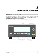
Chapter 2: PEM-100 Controller
16
PEM 100 User Manual
5
9
4
8
3
7
2
6
1
RS232TX
RS232RX
+5VL
R62
10K
J2
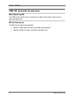
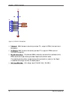
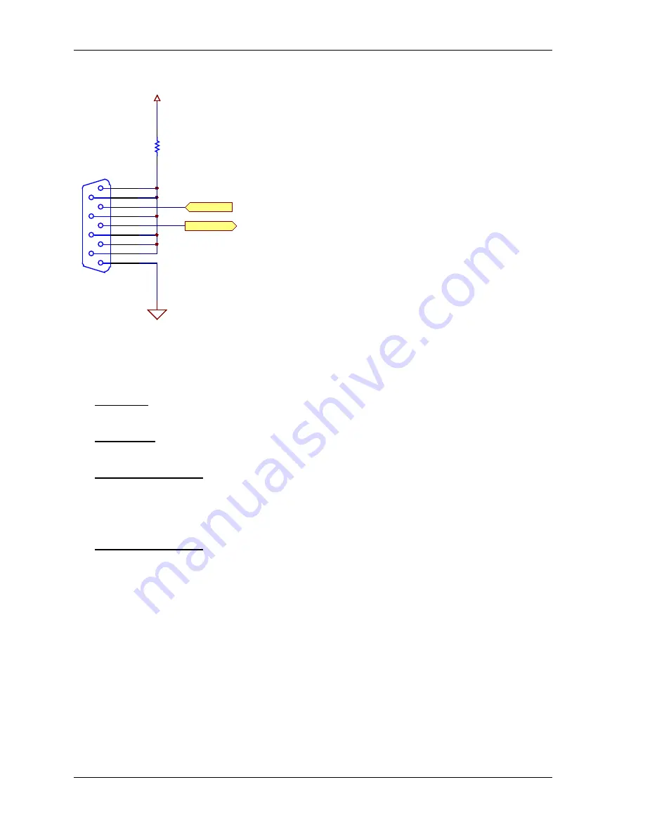
Figure 2.3 RS232 Connections
•
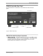
f Output:
BNC female connector provides TTL output of PEM, first harmonic
frequency.
•
2f Output:
BNC female connector provides TTL output of PEM, second
harmonic frequency.
•
Head Connection:
This female DB9 connector connects the controller to the
PEM electronic head via the provided Head-to-Controller cable.
The lightning bolt symbol, located above this connection, refers to the Head
connector as being a source of output power.
•
A/C Input Module:
AC voltage input 100-240 VAC, 50-60Hz.
Summary of Contents for PEM-100
Page 1: ...PEM 100 PHOTOELASTIC MODULATOR USER MANUAL Hinds Instruments Inc P N 010 0000 021 UM Rev H ...
Page 4: ......
Page 8: ...Table Of Contents viii PEM 100 User Manual ...
Page 12: ...Table of Tables xii PEM 100 User Manual ...
Page 22: ...Unpacking the PEM 100 10 PEM 100 User Manual ...
Page 46: ...Chapter 5 PEM 100 Controller Display 34 PEM 100 User Manual ...
Page 52: ...Chapter 6 Operating the PEM 100 Controller 40 PEM 100 User Manual ...
Page 68: ...Chapter 9 Troubleshooting 56 PEM 100 User Manual ...
Page 74: ...Chapter 10 Maintenance 62 PEM 100 User Manual ...
Page 88: ...Appendix A Calibration 76 PEM 100 User Manual ...
Page 92: ...Appendix C Optical HeadSpecifications 80 PEM 100 User Manual ...
Page 100: ......

