Chapter 3: Modulator Head Assembly
20
PEM 100 User Manual
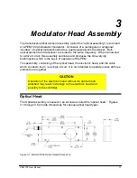
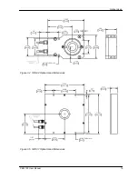
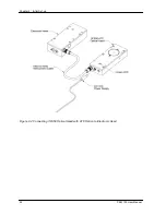
The optical head is connected to the electronic driver circuit (housed in the
“electronic head”) by a head-to-head Interconnect cable. This assembly of the
optical head, the electronic head, and the head-to-head interconnect cable
comprises the “modulator head,” which should be regarded as a single unit.
CAUTION
Operation of the electronic head without the head-to-head cable
and optical head connected should never be attempted. Such
operation will almost certainly result in damage to the electronic
head.
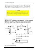
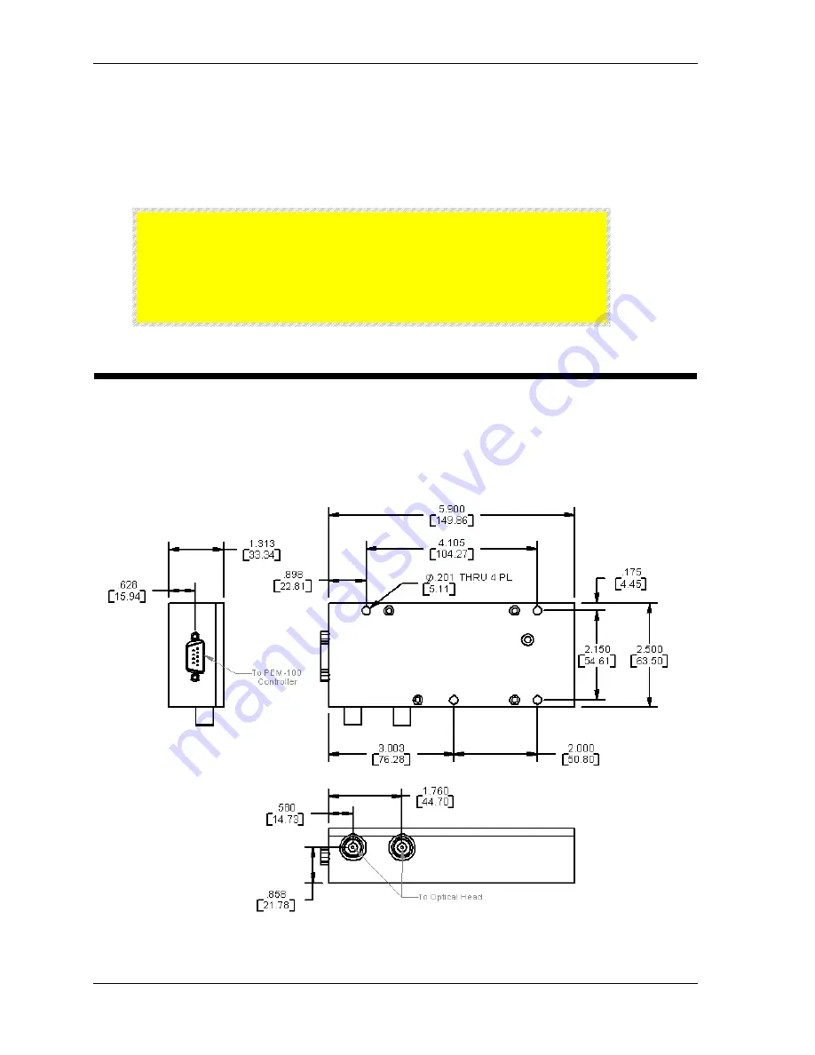
Electronic Head
The electronic head (driver circuit) consists of an active LC tank circuit connected in
parallel to the optical head. The head-to-head interconnect cable contributes
capacitance to the tank circuit. The electronic head also generates a current
feedback signal back to the controller.
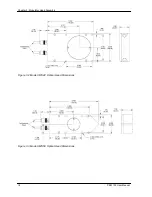
Figure 3.6 Electronic Head Dimensions
Summary of Contents for PEM-100
Page 1: ...PEM 100 PHOTOELASTIC MODULATOR USER MANUAL Hinds Instruments Inc P N 010 0000 021 UM Rev H ...
Page 4: ......
Page 8: ...Table Of Contents viii PEM 100 User Manual ...
Page 12: ...Table of Tables xii PEM 100 User Manual ...
Page 22: ...Unpacking the PEM 100 10 PEM 100 User Manual ...
Page 46: ...Chapter 5 PEM 100 Controller Display 34 PEM 100 User Manual ...
Page 52: ...Chapter 6 Operating the PEM 100 Controller 40 PEM 100 User Manual ...
Page 68: ...Chapter 9 Troubleshooting 56 PEM 100 User Manual ...
Page 74: ...Chapter 10 Maintenance 62 PEM 100 User Manual ...
Page 88: ...Appendix A Calibration 76 PEM 100 User Manual ...
Page 92: ...Appendix C Optical HeadSpecifications 80 PEM 100 User Manual ...
Page 100: ......

