PEM 100 User Manual
21
4
Initial Set-Up
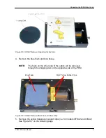
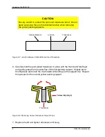
Before initial set-up, the PEM optic head should be unpackaged as described in
Unpacking the PEM Optical Head on page 4.
Connecting the PEM Optical and Electronic Heads
There are two different connection configurations between the optical head and
electronic head based upon the type of optical head used.
Depending upon your specific application, your head set may come with one of the
following head-to-head interconnect cable(s):
•
Single blue triaxial head-to-head interconnect cable
•
Dual black coaxial head-to-head interconnect cables
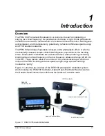
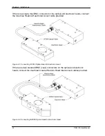
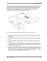
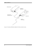
1. Connect the optical head to the electronic head by means of the Head-to-Head
interconnect cable. See figures 4.1 and 4.2 on the following page.
CAUTION
Operation of the modulator should never be attempted unless
this connection has been made. Such operation will almost
certainly result in damage to the electronic head.
Summary of Contents for PEM-100
Page 1: ...PEM 100 PHOTOELASTIC MODULATOR USER MANUAL Hinds Instruments Inc P N 010 0000 021 UM Rev H ...
Page 4: ......
Page 8: ...Table Of Contents viii PEM 100 User Manual ...
Page 12: ...Table of Tables xii PEM 100 User Manual ...
Page 22: ...Unpacking the PEM 100 10 PEM 100 User Manual ...
Page 46: ...Chapter 5 PEM 100 Controller Display 34 PEM 100 User Manual ...
Page 52: ...Chapter 6 Operating the PEM 100 Controller 40 PEM 100 User Manual ...
Page 68: ...Chapter 9 Troubleshooting 56 PEM 100 User Manual ...
Page 74: ...Chapter 10 Maintenance 62 PEM 100 User Manual ...
Page 88: ...Appendix A Calibration 76 PEM 100 User Manual ...
Page 92: ...Appendix C Optical HeadSpecifications 80 PEM 100 User Manual ...
Page 100: ......

