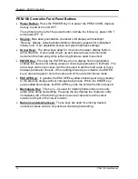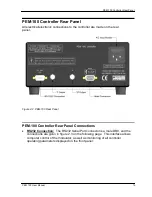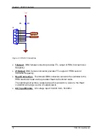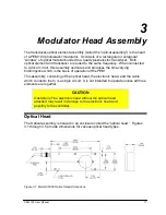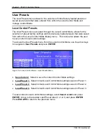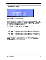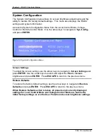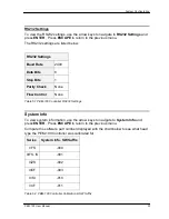
Chapter 4: Initial Set-up
22
PEM 100 User Manual
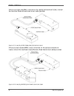
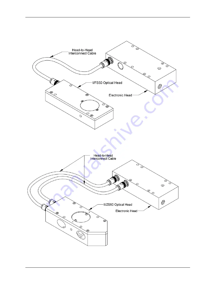
If there is a single, triax BNC connector on the optical and electronic heads, connect
the blue triax Head-to-Head Interconnect cable provided.
Figure 4.1 Connecting I/FS50 Optical Head to Electronic Head
If there are dual standard BNC (coax) connectors on the optical and electronic
heads, connect the dual black coaxial Head-to-Head Interconnect cables provided.
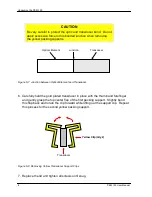
Figure 4.2 Connecting II/ZS50 Optical Head to Electronic Head
Summary of Contents for PEM-100
Page 1: ...PEM 100 PHOTOELASTIC MODULATOR USER MANUAL Hinds Instruments Inc P N 010 0000 021 UM Rev H ...
Page 4: ......
Page 8: ...Table Of Contents viii PEM 100 User Manual ...
Page 12: ...Table of Tables xii PEM 100 User Manual ...
Page 22: ...Unpacking the PEM 100 10 PEM 100 User Manual ...
Page 46: ...Chapter 5 PEM 100 Controller Display 34 PEM 100 User Manual ...
Page 52: ...Chapter 6 Operating the PEM 100 Controller 40 PEM 100 User Manual ...
Page 68: ...Chapter 9 Troubleshooting 56 PEM 100 User Manual ...
Page 74: ...Chapter 10 Maintenance 62 PEM 100 User Manual ...
Page 88: ...Appendix A Calibration 76 PEM 100 User Manual ...
Page 92: ...Appendix C Optical HeadSpecifications 80 PEM 100 User Manual ...
Page 100: ......

