Optical Bench Set-up
PEM 100 User Manual
25
Optical Bench Set-up
The optical bench and electronic configuration depend on the particular application
required for the modulator. More detailed set-up information can be found at our
website
http://www.hindsinstruments.com/applications
for an applications pull down
menu.
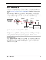
The most common optical and electronic setup for checkout and calibration of the
modulator is shown in figure 4.5. This shows a monochromatic light source (such as
a laser) or multiwavelength source with a wavelength selection device (e.g.
monochromator).
Monochromatic
Light Source
+45°
Polarizer
Modulator
0°
Polarizer
Controller
Oscilloscope
Reference
-45°
Detector
Figure 4.5 Block Diagram for Oscilloscope Calibration Method
The light source, if unpolarized, is followed by a polarizer at 45 degrees with respect
to the horizontal, the modulator with its axis horizontal (0 degrees), a second
polarizer (often called the analyzer) at -45 degrees, and a detector.
Functional Check
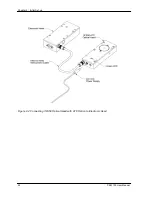
Figure 4.6 shows the basic electronic requirements. Most light sources will require
an electrical power supply, not discussed here. The detector is shown supplying a
signal to the oscilloscope, with the controller reference signal connected to the
oscilloscope trigger input.
Summary of Contents for PEM-100
Page 1: ...PEM 100 PHOTOELASTIC MODULATOR USER MANUAL Hinds Instruments Inc P N 010 0000 021 UM Rev H ...
Page 4: ......
Page 8: ...Table Of Contents viii PEM 100 User Manual ...
Page 12: ...Table of Tables xii PEM 100 User Manual ...
Page 22: ...Unpacking the PEM 100 10 PEM 100 User Manual ...
Page 46: ...Chapter 5 PEM 100 Controller Display 34 PEM 100 User Manual ...
Page 52: ...Chapter 6 Operating the PEM 100 Controller 40 PEM 100 User Manual ...
Page 68: ...Chapter 9 Troubleshooting 56 PEM 100 User Manual ...
Page 74: ...Chapter 10 Maintenance 62 PEM 100 User Manual ...
Page 88: ...Appendix A Calibration 76 PEM 100 User Manual ...
Page 92: ...Appendix C Optical HeadSpecifications 80 PEM 100 User Manual ...
Page 100: ......

