Chapter 4: Initial Set-up
26
PEM 100 User Manual
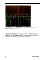
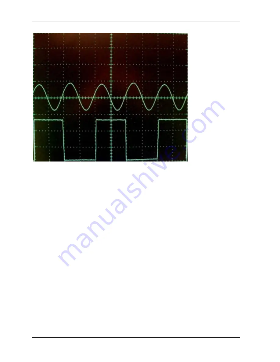
Figure 4.6 Oscilloscope Waveform for PEM Set to 0.25 Wave Retardation Between Crossed
Polarizers and PEM 1f Reference Signal
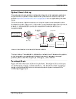
The detector circuitry deserves some special comment. Care must be taken to
ensure adequate frequency response, typically several times the PEM operating
frequency. Pre-amplified photo detectors are available from Hinds Instruments that
fit this need. See page 82 for contacting Hinds Instruments Inc.
Summary of Contents for PEM-100
Page 1: ...PEM 100 PHOTOELASTIC MODULATOR USER MANUAL Hinds Instruments Inc P N 010 0000 021 UM Rev H ...
Page 4: ......
Page 8: ...Table Of Contents viii PEM 100 User Manual ...
Page 12: ...Table of Tables xii PEM 100 User Manual ...
Page 22: ...Unpacking the PEM 100 10 PEM 100 User Manual ...
Page 46: ...Chapter 5 PEM 100 Controller Display 34 PEM 100 User Manual ...
Page 52: ...Chapter 6 Operating the PEM 100 Controller 40 PEM 100 User Manual ...
Page 68: ...Chapter 9 Troubleshooting 56 PEM 100 User Manual ...
Page 74: ...Chapter 10 Maintenance 62 PEM 100 User Manual ...
Page 88: ...Appendix A Calibration 76 PEM 100 User Manual ...
Page 92: ...Appendix C Optical HeadSpecifications 80 PEM 100 User Manual ...
Page 100: ......

