PEM 100 User Manual
57
10
Maintenance
Calibration
PEM-100 modulators are calibrated at the factory before shipment. For most
applications, recalibration is neither necessary nor appropriate. For a few
applications, however, an
on-site
calibration procedure will be necessary if optimum
performance is to be achieved. Hinds’ engineers will be glad to advise users on
whether on site calibration is appropriate in a particular case.
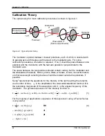
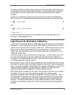
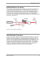
The Calibration appendix contains an extensive discussion of the theory of
retardation calibration and a variety of methods for establishing known calibration
points. Fortunately, photoelastic modulators are to a large extent self calibrating,
and most of the equipment needed for calibration will be required for the user’s
experiment.
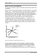
Adjustment of Peak Retardation Calibration
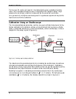
The most common reference point used for calibration is half-wave peak retardation
or an integral multiple of half-wave. This condition may be easily observed using an
oscilloscope, as described in the Calibration appendix. Even when other reference
points are used, this method should be regarded as the “coarse adjustment” on the
modulator calibration.
The peak retardation calibration of the modulator is adjusted by R4, a multi-turn
trimpot labeled “Range” in the electronic head. With the appropriate optical bench
setup and detection system, the trimpot is adjusted until the calibration condition is
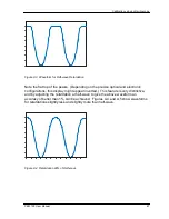
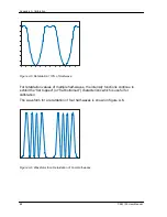
obtained. For example, in the case of the half-wave calibration, the appropriate flat
toped (or flat bottomed) characteristic waveform is observed on the oscilloscope.
Maintenance
The optical head contains an optical element and requires the same care in use as
other components such as lenses and mirrors. The unit should not be operated in a
dusty, corrosive, or otherwise contaminating environment. Small amounts of dust
may be removed from the optical element with a soft brush such as an artist’s
camel-hair brush. If more serious contamination occurs, contact Hind’s engineers.
The PEM units are rugged and reliable and normally require no additional
maintenance. If trouble occurs, please consult the troubleshooting section and then
contact Hinds’ engineers for assistance.
Summary of Contents for PEM-100
Page 1: ...PEM 100 PHOTOELASTIC MODULATOR USER MANUAL Hinds Instruments Inc P N 010 0000 021 UM Rev H ...
Page 4: ......
Page 8: ...Table Of Contents viii PEM 100 User Manual ...
Page 12: ...Table of Tables xii PEM 100 User Manual ...
Page 22: ...Unpacking the PEM 100 10 PEM 100 User Manual ...
Page 46: ...Chapter 5 PEM 100 Controller Display 34 PEM 100 User Manual ...
Page 52: ...Chapter 6 Operating the PEM 100 Controller 40 PEM 100 User Manual ...
Page 68: ...Chapter 9 Troubleshooting 56 PEM 100 User Manual ...
Page 74: ...Chapter 10 Maintenance 62 PEM 100 User Manual ...
Page 88: ...Appendix A Calibration 76 PEM 100 User Manual ...
Page 92: ...Appendix C Optical HeadSpecifications 80 PEM 100 User Manual ...
Page 100: ......

