Light Sources for Modulator Calibration
PEM 100 User Manual
65
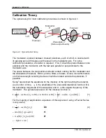
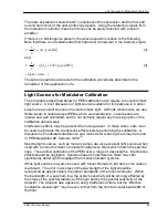
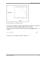
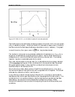
The latter expression shows the DC component of the expression and the first and
second harmonics of the optical intensity signals. Using the reference signals from
the modulator controller, these harmonics can be easily detected with a lock-in
amplifier.
If there is no birefringence present, the above equations reduce to the following.
Note that there is no fundamental (first harmonic) component in the intensity signal.
(
)
{
}
t
A
I
Ω
−
=
cos
cos
1
2
1
0
(3)
and
( )
{
( ) (
)
t
A
J
A
J
I
Ω
+
−
=
2
cos
2
2
1
2
1
0
0
0
(4)
higher
+
}
..
terms
These four equations are basis for the calibration procedures described in the
remainder of this application note.
Light Sources for Modulator Calibration
The procedures described below for PEM calibration each require a monochromatic
light source. A brief discussion of light sources suitable for this purpose is in order.
Lasers are excellent sources of monochromatic light. At Hinds Instruments, we use
HeNe lasers to calibrate most PEMs which we manufacture. Laser beams are
intense and well collimated, and do not normally require any focusing optics in the
calibration optical setup.
Interference effects may be present when using a laser. In those cases, care must
be used to eliminate the interference effects before performing the calibration. A
discussion of modulated interference and methods for reducing them may be found
in PEM Newsletter #8, Summer 1998
(2)
.
Spectral light sources, such as mercury lamps, are also excellent light sources when
used with a monochromator or selected interference filters which match the spectral
lines. These allow calibration of the PEM over a range of wavelengths. Interference
effects should be negligible. Systems based on interference filters may offer
significantly better light throughput than monochromator systems.
White light sources may also be used with monochromators, but here some caution
is advised. The error in accuracy of the wavelength of the light should be
recognized as approximately the optical bandwidth of the monochromator. Within
the bandwidth of a spectrum line, the system sensitivity will be strongly affected by
the slope of the spectral radiance of the light and by the spectral sensitivity of the
detector. The situation also applies to using interference filters, but the “effective
modulation wavelength” may be even further from the nominal center bandwidth of
the filter.
Summary of Contents for PEM-100
Page 1: ...PEM 100 PHOTOELASTIC MODULATOR USER MANUAL Hinds Instruments Inc P N 010 0000 021 UM Rev H ...
Page 4: ......
Page 8: ...Table Of Contents viii PEM 100 User Manual ...
Page 12: ...Table of Tables xii PEM 100 User Manual ...
Page 22: ...Unpacking the PEM 100 10 PEM 100 User Manual ...
Page 46: ...Chapter 5 PEM 100 Controller Display 34 PEM 100 User Manual ...
Page 52: ...Chapter 6 Operating the PEM 100 Controller 40 PEM 100 User Manual ...
Page 68: ...Chapter 9 Troubleshooting 56 PEM 100 User Manual ...
Page 74: ...Chapter 10 Maintenance 62 PEM 100 User Manual ...
Page 88: ...Appendix A Calibration 76 PEM 100 User Manual ...
Page 92: ...Appendix C Optical HeadSpecifications 80 PEM 100 User Manual ...
Page 100: ......


