Appendix A: Calibration
74
PEM 100 User Manual
A
0
V
2f
/ V
DC
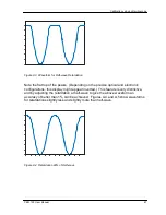
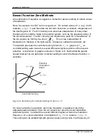
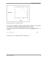
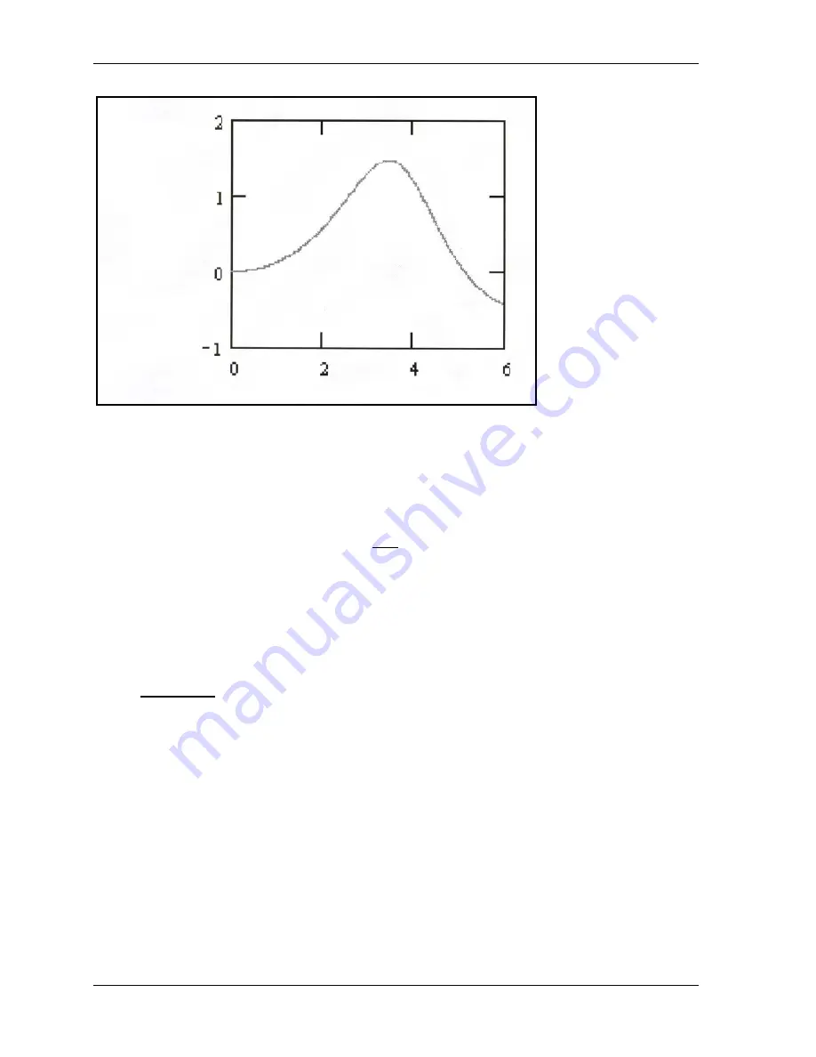
Figure A.10 Ratio V
2f
/V
DC
vs. retardation (radians) for parallel polarizers
This method gives monotonically increasing values of the ratio V
2f
/V
DC
for low values
of A
0
(3 radians and less). It lacks sensitivity for retardation values near 3.5 radians,
but this is where the flat-topped half-wave waveform occurs (
π
radians). The graph
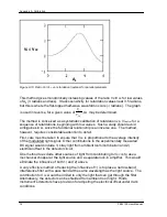
is used in reverse, for a given value of
DC
f
V
V
2
, A
0
may be determined.
The method is conceived as a systematic calibration of retardation vs. V
Control
for a
sequence of retardations, beginning with low values. Such a study should avoid
ambiguities in A, since the functional relationship is an inverse one. The method,
however, requires considerable attention to detail.
First, care must be taken to ensure that V
DC
is proportional to the average intensity
of the modulated light signal. Other contributions to the experimentally measured
DC signal would include 1) stray light from ambient room illumination and 2)
electrical offset in the detector circuit.
One method to exclude other sources of light from contributing to V
DC
is to use a
mechanical chopper at the light source and a separate lock-in amplifier. This would
eliminate the influence of both 1) and 2) above.
A very effective method of reducing the influence of 1) is to place a narrow-band
interference filter with a pass band at the same wavelength as the light source. The
contribution to V
DC
would be limited to only the light that can get through the filter.
Alternatively, the detector can be shielded from ambient room light. Hinds
Instrument’s detectors have provision for adjusting the electrical offset under dark
conditions.
Summary of Contents for PEM-100
Page 1: ...PEM 100 PHOTOELASTIC MODULATOR USER MANUAL Hinds Instruments Inc P N 010 0000 021 UM Rev H ...
Page 4: ......
Page 8: ...Table Of Contents viii PEM 100 User Manual ...
Page 12: ...Table of Tables xii PEM 100 User Manual ...
Page 22: ...Unpacking the PEM 100 10 PEM 100 User Manual ...
Page 46: ...Chapter 5 PEM 100 Controller Display 34 PEM 100 User Manual ...
Page 52: ...Chapter 6 Operating the PEM 100 Controller 40 PEM 100 User Manual ...
Page 68: ...Chapter 9 Troubleshooting 56 PEM 100 User Manual ...
Page 74: ...Chapter 10 Maintenance 62 PEM 100 User Manual ...
Page 88: ...Appendix A Calibration 76 PEM 100 User Manual ...
Page 92: ...Appendix C Optical HeadSpecifications 80 PEM 100 User Manual ...
Page 100: ......

