PEM 100 User Manual
ix
Table of Figures
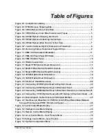
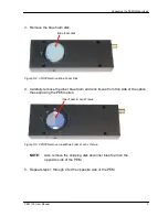
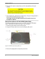
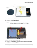
Figure S.3 I/FS50 Remove Inner Blue Foam & Lens Tissue ........................................... 5
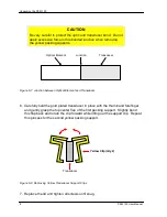
Figure S.7 Junction between Optical Element and Transducer ..................................... 8
Figure 4.1 Connecting I/FS50 Optical Head to Electronic Head ....................................22
Figure 4.2 Connecting II/ZS50 Optical Head to Electronic Head ...................................22
Figure 4.3 Connecting II/ZS50 Optical Head to Electronic Head (Cross Connection) .23
Figure 4.4 Connecting 1/FS50 Optical Head with ATC Option to Electronic Head ......24
Figure 4.5 Block Diagram for Oscilloscope Calibration Method ...................................25
Figure 4.6 Oscilloscope Waveform for PEM Set to 0.25 Wave Retardation Between
Crossed Polarizers and PEM 1f Reference Signal ..................................................26
Summary of Contents for PEM-100
Page 1: ...PEM 100 PHOTOELASTIC MODULATOR USER MANUAL Hinds Instruments Inc P N 010 0000 021 UM Rev H ...
Page 4: ......
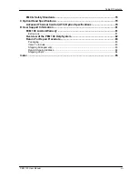
Page 8: ...Table Of Contents viii PEM 100 User Manual ...
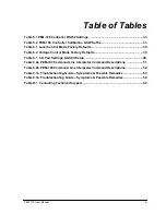
Page 12: ...Table of Tables xii PEM 100 User Manual ...
Page 22: ...Unpacking the PEM 100 10 PEM 100 User Manual ...
Page 46: ...Chapter 5 PEM 100 Controller Display 34 PEM 100 User Manual ...
Page 52: ...Chapter 6 Operating the PEM 100 Controller 40 PEM 100 User Manual ...
Page 68: ...Chapter 9 Troubleshooting 56 PEM 100 User Manual ...
Page 74: ...Chapter 10 Maintenance 62 PEM 100 User Manual ...
Page 88: ...Appendix A Calibration 76 PEM 100 User Manual ...
Page 92: ...Appendix C Optical HeadSpecifications 80 PEM 100 User Manual ...
Page 100: ......


