Unpacking the PEM-100
8
PEM 100 User Manual
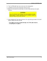
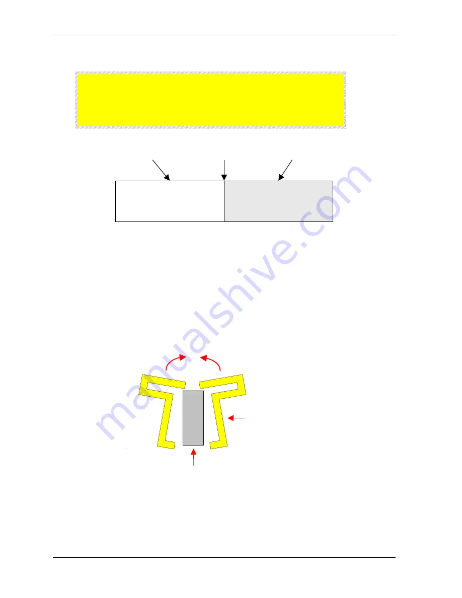
CAUTION
Be very careful to protect the optic and transducer bond. Do not
apply excessive force to this bonded junction when removing
the yellow packing supports.
Transducer
Optical Element
Junction
Figure S.7 Junction between Optical Element and Transducer
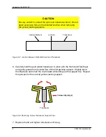
6. Carefully hold the gold plated transducer in place with the thumb and forefinger
and gently grasp the top center flap of the first packing support. Slightly bend
this flap back and rotate the clip forward while lifting out the support clip. Repeat
this process for the second yellow packing support.
Transducer
Yellow Clip (Qty 2)
Figure S.8 Removing Yellow Transducer Support Clips
7. Replace the lid and tighten all screws until snug.
Summary of Contents for PEM-100
Page 1: ...PEM 100 PHOTOELASTIC MODULATOR USER MANUAL Hinds Instruments Inc P N 010 0000 021 UM Rev H ...
Page 4: ......
Page 8: ...Table Of Contents viii PEM 100 User Manual ...
Page 12: ...Table of Tables xii PEM 100 User Manual ...
Page 22: ...Unpacking the PEM 100 10 PEM 100 User Manual ...
Page 46: ...Chapter 5 PEM 100 Controller Display 34 PEM 100 User Manual ...
Page 52: ...Chapter 6 Operating the PEM 100 Controller 40 PEM 100 User Manual ...
Page 68: ...Chapter 9 Troubleshooting 56 PEM 100 User Manual ...
Page 74: ...Chapter 10 Maintenance 62 PEM 100 User Manual ...
Page 88: ...Appendix A Calibration 76 PEM 100 User Manual ...
Page 92: ...Appendix C Optical HeadSpecifications 80 PEM 100 User Manual ...
Page 100: ......

