Chapter 2: PEM-100 Controller
14
PEM 100 User Manual
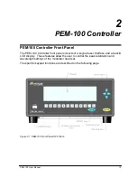
PEM-100 Controller Front Panel Buttons
•
Power Button:
Press the POWER key in to power the PEM-100 ON, depress
the key to power the unit OFF.
The symbols to the left of the power button indicate the following: power ON ‘I’
and power OFF ‘O’.
•
Display:
Blue background/white character LCD display with backlight.
‘Reverse’ display, white background/blue character, appears for highlighted
display field. User adjustable screen and pixel brightness settings.
•
Arrow Keys:
The arrow keys allow for movement between display fields in
arrow direction. Once inside a field, up and down arrows increment and
decrement the field entry while left and right arrows allow movement.
•
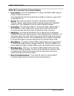
ENTER Key:
Pressing the ENTER key when a display field is highlighted
enables the process for editing values or choosing parameters in that field. The
arrow keys and numeric keys can then be used to edit the field value or move
between parameter choices. When editing/choosing is complete, the ENTER
key is pressed again to store the value and shift out of edit/choose mode.
•
ESCAPE Key:
In general, the ESCAPE key allows backing out of any display
to the previous display without changes being made. While the ENTER key
saves edited field values, the ESCAPE key exits the field with edits not saved.
•
Backspace Key:
This key [
←] is used for deleting field entries and is only
active while doing field editing. Pressing the key deletes the character entry
immediately left of the blinking cursor as well as characters at the cursor
location and right of the cursor location.
•
Numeric and decimal keys:
These keys are used for entering desired
numerical values and are only active while doing field editing.
Summary of Contents for PEM-100
Page 1: ...PEM 100 PHOTOELASTIC MODULATOR USER MANUAL Hinds Instruments Inc P N 010 0000 021 UM Rev H ...
Page 4: ......
Page 8: ...Table Of Contents viii PEM 100 User Manual ...
Page 12: ...Table of Tables xii PEM 100 User Manual ...
Page 22: ...Unpacking the PEM 100 10 PEM 100 User Manual ...
Page 46: ...Chapter 5 PEM 100 Controller Display 34 PEM 100 User Manual ...
Page 52: ...Chapter 6 Operating the PEM 100 Controller 40 PEM 100 User Manual ...
Page 68: ...Chapter 9 Troubleshooting 56 PEM 100 User Manual ...
Page 74: ...Chapter 10 Maintenance 62 PEM 100 User Manual ...
Page 88: ...Appendix A Calibration 76 PEM 100 User Manual ...
Page 92: ...Appendix C Optical HeadSpecifications 80 PEM 100 User Manual ...
Page 100: ......


