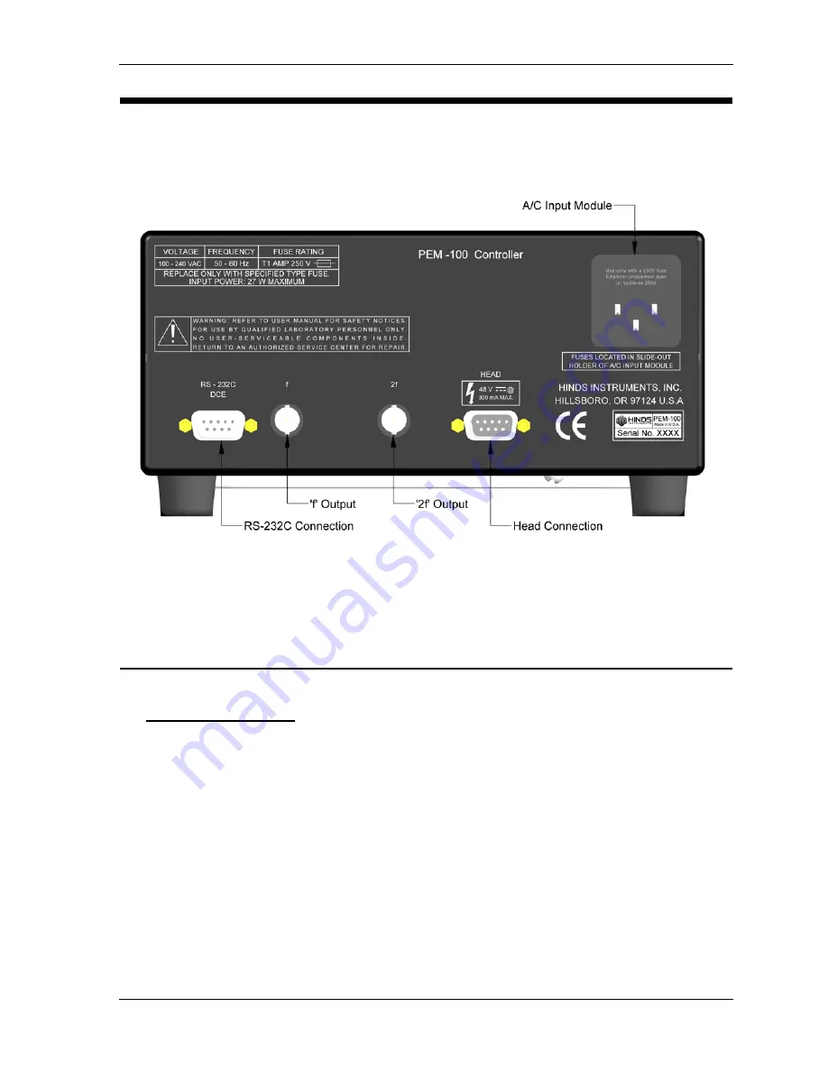
PEM-100 Controller Rear Panel
PEM 100 User Manual
15
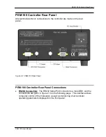
PEM-100 Controller Rear Panel
All electrical/electronic connections to the controller are made on the rear
panel.
Figure 2.2 PEM-100 Rear Panel
PEM-100 Controller Rear Panel Connections
•
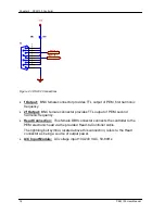
RS232 Connection:
The RS232 Serial Port connector is a male DB9, and the
connections are given in figure 2.3 on the following page. This interface allows
computer control of the modulator, as well as monitoring of all controller
operating parameters displayed on the front panel.
Summary of Contents for PEM-100
Page 1: ...PEM 100 PHOTOELASTIC MODULATOR USER MANUAL Hinds Instruments Inc P N 010 0000 021 UM Rev H ...
Page 4: ......
Page 8: ...Table Of Contents viii PEM 100 User Manual ...
Page 12: ...Table of Tables xii PEM 100 User Manual ...
Page 22: ...Unpacking the PEM 100 10 PEM 100 User Manual ...
Page 46: ...Chapter 5 PEM 100 Controller Display 34 PEM 100 User Manual ...
Page 52: ...Chapter 6 Operating the PEM 100 Controller 40 PEM 100 User Manual ...
Page 68: ...Chapter 9 Troubleshooting 56 PEM 100 User Manual ...
Page 74: ...Chapter 10 Maintenance 62 PEM 100 User Manual ...
Page 88: ...Appendix A Calibration 76 PEM 100 User Manual ...
Page 92: ...Appendix C Optical HeadSpecifications 80 PEM 100 User Manual ...
Page 100: ......

