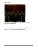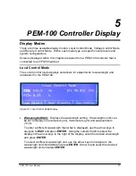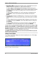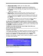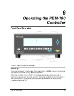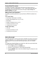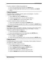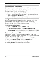
Optical Bench Set-up
PEM 100 User Manual
23
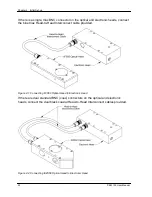
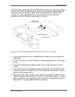
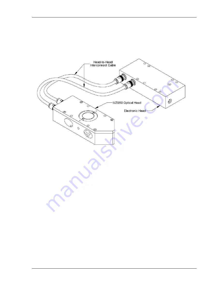
If the dual black coaxial Head-to-Head Interconnect cables are ‘crossed’ as shown in
figure 4.3, the instrument will operate correctly, except that the phase relationship
between the optical retardation signal and the phase reference outputs will be
inverted. For many applications this is not a problem, or can be used as a
diagnostic tool when tracing the signal path in a system.
Figure 4.3 Connecting II/ZS50 Optical Head to Electronic Head (Cross Connection)
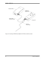
2. Connect the electronic head to the PEM-100 Controller using the Controller-to-
Head cable.
3. Connect the power cord to the PEM-100 Controller and plug it into an AC power
source.
4. Connect the RS232 serial interface cable to the computer (if used for remote
control).
5. If the optical head came equipped with ATC (Advanced Thermal Control), then
connect the power cord of the 24V DC power supply that came with the optical
head into an AC power source.
6. Plug in the output of the 24V DC power supply into the power receptacle on the
side of the optical head as shown in Figure 4.4 on the following page. The green
LED should flash on and off indicating the optical head temperature is ramping
towards 32º C, the green LED will remain on steady.
Summary of Contents for PEM-100
Page 1: ...PEM 100 PHOTOELASTIC MODULATOR USER MANUAL Hinds Instruments Inc P N 010 0000 021 UM Rev H ...
Page 4: ......
Page 8: ...Table Of Contents viii PEM 100 User Manual ...
Page 12: ...Table of Tables xii PEM 100 User Manual ...
Page 22: ...Unpacking the PEM 100 10 PEM 100 User Manual ...
Page 46: ...Chapter 5 PEM 100 Controller Display 34 PEM 100 User Manual ...
Page 52: ...Chapter 6 Operating the PEM 100 Controller 40 PEM 100 User Manual ...
Page 68: ...Chapter 9 Troubleshooting 56 PEM 100 User Manual ...
Page 74: ...Chapter 10 Maintenance 62 PEM 100 User Manual ...
Page 88: ...Appendix A Calibration 76 PEM 100 User Manual ...
Page 92: ...Appendix C Optical HeadSpecifications 80 PEM 100 User Manual ...
Page 100: ......

