Service 27
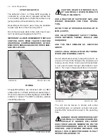
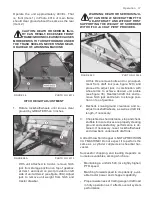
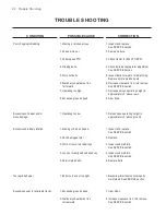
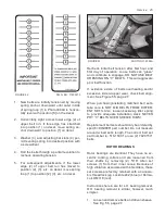
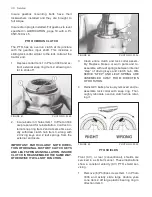
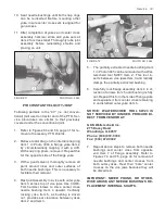
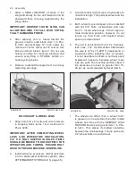
FIGURE 56 PHOTO NO. 3010B
IMPORTANT: DO NOT USE LUBRICANTS, ANTI
SEIZE, AND/OR EXCESSIVE BOLT TORQUE
WHEN ASSEMBLING Q.D. SHEAVES. THESE
CAN BREAK THE ASSEMBLY.
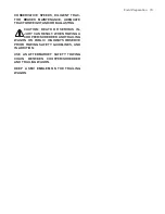
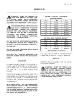
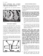
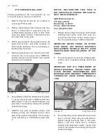
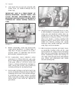
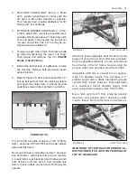
6. Install driveN sheave Item 4 in Photo 3010C
OUTBOARD of bushing’s Item 2 flange. In-
stall driven sheave Item 3 in photo 3010C IN-
BOARD of bushing’s Item 1 flange.
7. Insure woodruff key is in place before sliding
inner bushing on shaft. Align (in/out) the Allen
set screw hole of the bushing being installed
with existing witness marks on its shaft and
torque the set screw.
8. Align 3 UNTHREADED bolt holes Items 5 or 6
with THREADED bolt holes in mating sheave
or bushing. Insert bolts and lockwashers
in these UNTHREADED holes and tighten
about 2 turns each.
9. Alternately torque these bolts, in a uniform
pattern, until the tapers are seated (approxi-
mately 1/2 bolt torque). Check for sheave
alignment and possible wobble. Correct if
necessary.
IMPORTANT: SHEAVE BOLTS ARE ONLY
TORQUED TO GRADE 2 VALUES OF 18-24 Ft./
Lbs. (24-33 N/m.).
10. Continue bolt torquing until above values oc-
cur, or NO LESS THAN 1/8” HUB FLANGE
TO SHEAVE CLEARANCE EXISTS. There
will always be a gap in the inner bushing hub
when proper procedure is followed.
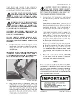
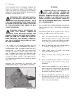
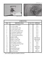
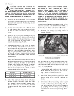
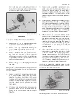
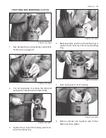
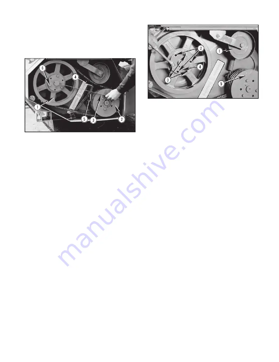
4. Refer to Figure 56, for sheave loosening
procedure and adjust driveR sheave’s in-
ner bushing Item 6 in Photo 3009A in or out
as required for realignment. Then reinstall
sheave per Figure 57, page 28.
FIGURE 55 PHOTO NO. 3009A
SHEAVES REMOVAL/INSTALLATION
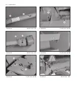
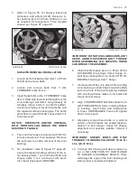
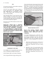
1. Loosen belt’s backwrap idler Item 1 in Photo
3010B and remove belts.
2. Loosen and remove bolts from 3 UN-
THREADED holes Item 2.
3. Insert these bolts in the 3 THREADED holes
Item 3. Start with the bolt furtherest from the
inner bushing’s slot Item 4 and gradually al-
ternately torque bolts in a uniform pattern.
Continue torquing in small increments until
the tapered surfaces disengage. The same
procedure is used if driveN sheave Item 5 is
to be removed.
NOTICE: EXCESSIVE AND/OR UNEQUAL
BOLT TORQUES CAN BREAK THE INNER
BUSHING’S FLANGE.
4. The inner bushings are retained with 3/8” Al-
len set screws over their keyways. Remove
the set screw to enable removal of the inner
bushing.
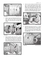
5. For installation refer to Figure 57 page 28,
insure the tapered mating surfaces of the in-
ner bushing Items 1 or 2 in Photo 3010C and
sheave Items 3 or 4 are free of dirt, paint,
rust, metal chips and LUBRICANT.
Summary of Contents for 5710
Page 2: ......
Page 50: ...NOTES 48 Notes ...

