40 Assembly
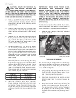
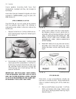
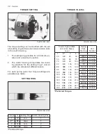
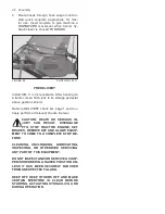
1. Allow a SMALL AMOUNT of slack in the
sling and slowly tip the unit forward until its
downward force is being supported by the
sling chains.
IMPORTANT: GROSSLY LOOSE SLING CAN
ALLOW MACHINE TO FALL WITH POTEN-
TIALLY DAMAGING FORCE.
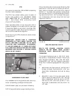
2. After allowing unit to rotate toward the
ground, insert a solid block Item 1 in Pho-
to 3221 approximately 12” high under the
machine’s center. Allow unit to rest on this
block and both blocks Item 2. Do not use
hollow concrete for machine blocking and
ensure everything is STABLE before un-
hooking sling chains.
3. Remove rockshaft dunnage Item 3 and any
remaining dunnage.
FIGURE 78 PHOTO NO. 3221
ROCKSHAFT & WHEEL LEGS
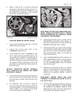
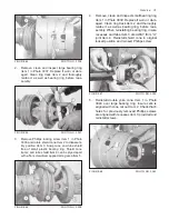
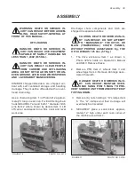
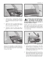
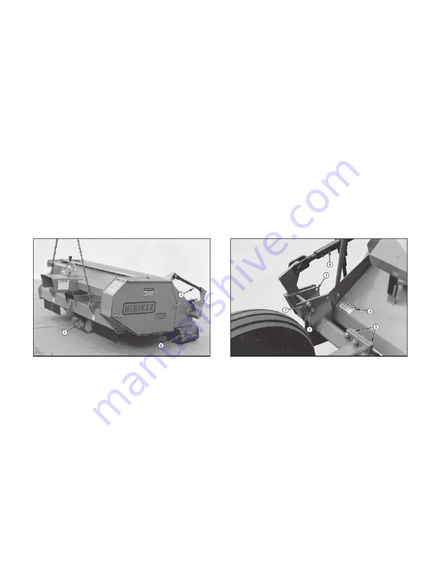
1. Allow both 5/8” x 6” bolts and nuts to remain
in shipping holes Items 1 & 2 as shown in
Photo 3236.
IMPORTANT: AFTER COMPLETING WHEEL
LEGS AND WHEEL/TIRE INSTALLATION,
5/8” X 6” BOLT SHIPPED IN HOLES ITEM 2
SHOULD BE MOVED TO HOLES ITEM 3 FOR
OPERATION AND TOWING. ENSURE BOLT
HEAD IS TOWARD MACHINE CENTERLINE.
2. Install either an accessory ratchet jack Item
4 or an aftermarket hydraulic cylinder. (See
AFTERMARKET HYDRAULICS, page 45.)
3. Contract either ratchet jack or hydraulics to
minimum length. This permits wheel and tire
installation.
4. Each wheel leg is clamped to the rockshaft
with (6) 5/8” bolts, lockwashers and nuts
Item 5. Install wheel legs in their approxi-
mate transverse position; however, do not
torque up their bolts until desired wheel
spacing is determined.
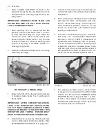
5. The unit is furnished with (2) 15 x 5 wheels,
less tires. The recommended aftermarket
tire size is 6.70 x 15-4PR l1 (implement) or
equivalent. After installing tires on wheels,
it is not desirable to inflate to normally used
implement pressure because wheel load-
ings are light. The machine performs best if
tire pressures are kept no greater than 15-
20 psi, as recommended by decal Item 6.
FIGURE 79 PHOTO NO. 3236
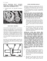
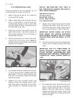
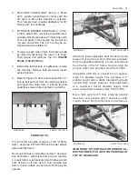
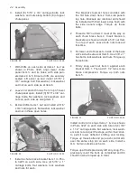
1. The wheels are offset, that is, wheel “dish”
is greater on one side than the other. Install
wheels and tires with the DEEPEST DISH
TOWARD the wheel leg as at Item 1 in Pho-
to 3214. This places its loaded centerline
between the hub bearings. Torque up the (6)
1/2” wheel bolts on each wheel.
Summary of Contents for 5710
Page 2: ......
Page 50: ...NOTES 48 Notes ...

