background image

SKID STEER LOADER VERSAPLOW

MODELS 4208, 4210

OPERATOR’S MANUAL

DO NOT USE OR OPERATE THIS EQUIPMENT UNTIL THIS MANUAL

HAS BEEN READ AND THOROUGHLY UNDERSTOOD

PART NUMBER 27000355

Summary of Contents for VERSAPLOW 4208

Page 1: ...SKID STEER LOADER VERSAPLOW MODELS 4208 4210 OPERATOR S MANUAL DO NOT USE OR OPERATE THIS EQUIPMENT UNTIL THIS MANUAL HAS BEEN READ AND THOROUGHLY UNDERSTOOD PART NUMBER 27000355 ...

Page 2: ......

Page 3: ...AFETY 3 OPERATING PROCEDURES 4 8 MAINTENANCE 9 10 TROUBLE SHOOTING 11 VERSAPLOW ASSEMBLY 12 15 SPECIFICATIONS 16 WIRING DIAGRAM 17 HYDRAULIC DIAGRAMS 18 ELECTRICAL PIN LAYOUT 19 WARRANTY 21 Table of Contents 1 27000355 9 19 MANUALS 27000355 ...

Page 4: ... YOUR SAFETY IS INVOLVED SAFETY SIGNAL WORDS DANGER Indicates an imminently hazardous situation that if not avoided will result in death or serious injury WARNING Indicates a potentially hazardous situation that if not avoided could result in death or serious injury CAUTION Indicates a potentially hazardous situation that if not avoided may result in minor or moderate injury or damage to component...

Page 5: ...afely and have the proper tools for the job 5 Do not service or otherwise handle a plow in the raised position unless it is securely blocked against unexpected falling 6 Keep hands feet hair and clothing away from moving parts 7 Do not alter the equipment to the extent of compromising safety or performance SAFETY Safety 3 BEFORE OPERATION 1 Discipline yourself to visually check for worn damaged or...

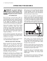
Page 6: ...s on the skid steer loader Reverse oil flow to angle the blade the opposite direction Release the hydraulic flow controller to hold the blade at an angle position between full left or full right If the plow angles opposite from what is expected switch couplers on the two feed hoses that connect to the loader 4 Operating Procedures When using a 7 or 14 pin harness that operates the plow through the...

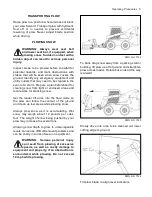
Page 7: ... mark obstructions with stakes that will be seen when snow covers the ground Identify any emergency equipment and utility outlets that may need to be cleared in the event of a storm Prepare a plan beforehand for clearing snow from tight or enclosed areas and locate sites for stacking snow Set the loader lift arms into the float mode so the plow can follow the contour of the ground and clean up low...

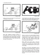
Page 8: ... snow until a working area is cleared Work small areas in multiple passes to push snow to outer edges Generally 6 inch snow accumulation can be plowed with the entire blade width 9 inch snow accumulation with 3 4 of the blade width 12 inch snow accumulation with 1 2 of the blade width Local conditions will determine how much work can be done before stalling or losing tire traction DWG NO 7745 Slow...

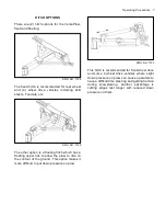
Page 9: ... is cutting edges last longer with reduced down pressure on them HITCH OPTIONS There are 2 hitch options for the VersaPlow fixed and floating DWG NO 7748 The fixed hitch is recommended for rear wheel and 4 wheel drive vehicles including skid steers Toolcats etc DWG NO 7749 The other option is a floating hitch which has a floating upper link to allow the plow to ride on the contour of the ground Th...

Page 10: ... plow cutting edge to the ground with plow edge on ground and 1 4 shims under box wing cutting edges Tighten 1 2 carriage bolts until metal on outside plates slightly deforms into slots of cutting edges This will prevent cutting edges from sliding up or down during operation Perform similar procedure to check back drag cutting edge heights Adjust as needed and again tighten hardware so outside pla...

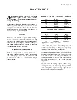
Page 11: ... been stored inspect all hardware and verify proper torque on all bolts and nuts in accordance with the recommended torque specifications Maintenance 9 GRADE 5 TYPE B F LOCK NUT TORQUES Size Ft lbs N m 5 16 13 18 17 25 3 8 23 33 31 44 1 2 58 82 79 112 5 8 117 165 158 223 GRADE 5 BOLT TORQUES Size Ft lbs N m 1 4 8 12 11 16 3 8 29 41 39 56 1 2 73 103 99 140 5 8 146 206 198 279 Applications without lo...

Page 12: ...The use of dielectric grease is recommended to reduce corrosion of the contacts and to make connecting and disconnecting easier Before each season check loader battery and electrical system for proper operation A weak battery dirty terminals or faulty charging system may cause improper operation LUBRICATION Periodically throughout the year between snowfalls grease all pivot points on plow as shown...

Page 13: ...place battery B Add oil do not overfill C Tighten or redo connection D Replace valve A Switch quick couplers on feed hoses A Tighten packing nut 1 8 turn B Repack or replace cylinder A Have relief pressure adjusted by skidsteer dealer A Loader arms should be in float mode A Locate and repair A Verify matching couplers B Relieve hydraulic pressure in loader POSSIBLE CAUSE A Weak or defective loader b...

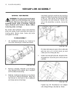
Page 14: ...APLOW ASSEMBLY GENERAL INFORMATION WARNING To prevent personal injury or death be certain to keep clear of any parts that may drop when removing bundling straps wires or brackets Support heavy sections with hoist or blocks before removing wires or straps Be certain that hydraulic hoses and electrical wires are safely routed and allow full motion of moving parts Secure loose hoses and wires with pl...

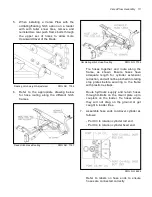
Page 15: ...tch Hose Routing DWG NO 7758 Tie hoses together and route along the frame as shown Ensure hoses have adequate length for cylinder extension retraction and will not be pinched in rotating stop plates before securing to the frame with plastic tie straps Route hydraulic supply and return hoses through U Bolts on the mount plate up to couplers on the loader Tie hoses where they will not drag on the gr...

Page 16: ... terminal to the negative post of the battery Ensure all wires are away from hot or moving parts and secured with plastic ties to prevent damage The wiring on the plow comes preinstalled The connectors to the solenoids should be firmly seated The connectors are interchangeable as both solenoids are activated at the same time when the push button switch is pressed 8 Attach two leveling bars onto the...

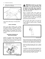
Page 17: ...on Perform similar procedure to check back drag cutting edge heights Adjust as needed and again tighten hardware so outside plates slightly deform to hold urethane cutting edge in place Refer to Operating Procedures section for attaching and operating the plow Test that all functions are working properly and that cabling is not being stretched or pinched 14 PIN OR 7 PIN ELECTRICAL HARNESS Locate 7...

Page 18: ...ght 30 1 2 30 1 2 30 1 2 30 1 2 Weight Moldboard Wings Only 807 lbs 938 lbs 911 lbs 1 075 lbs Weight Fixed Hitch 311 lbs Weight Floating Hitch 474 lbs Cutting Edge 1 1 2 x 8 Polyurethane 1 2 x 6 Steel 1 1 2 x 8 Polyurethane 1 2 x 6 Steel Feed Hose Ends 9 16 18 JIC Female Swivel Wiring Harness Fuse 10 AMP 16 Specifications ...

Page 19: ...TITLE Section 17 Wiring Diagram 17 DWG NO 4286 UNIVERSAL CONTROLLER WIRING DIAGRAM ...

Page 20: ...18 Hydraulic Diagrams DWG NO 7618 ...

Page 21: ... C SW BWD John Deere Gnd N A Right Down Left Down Kubota 14 Pin SVL75 90 95 Standard N A Gnd LH Switch RH Switch Kubota Extended 14 Pin Add On Kit N A Gnd Button 1 Button 2 New NH 14 Pin N A Gnd LH 3 Dn LH 3 Up Old NH 14 Pin N A Gnd SW3 MOM Dn SW MOM Up Takeuchi N A Gnd SW1 Up R Joy L Up SW 1 Dn R Joy L Down Yanmer N A Gnd SW1 Up SW 1 Dn Mustang N A Gnd SW1 Up SW 1 Dn Gehl SW 4 Gnd SW1 Up SW 1 Dn ...

Page 22: ...20 Notes NOTES ...

Page 23: ...bstitution of parts not approved by Hiniker or any alteration or repair in such manner as in our judgment affects the product materially and adversely shall void this warranty Hiniker reserves the right to make improvements or changes to any of it s products without notice Such improvements or changes shall not trigger any obligation by Hiniker to update modify or change any products previously so...

Reviews: