IMPORTANT: Damage to the wiring
harness will occur if adequate cable
length is not provided to allow for
full motion of the loader arms. Use plastic
tie straps to secure the wiring harness to
the loader arm immediately adjacent to the
loader arm pivot point.
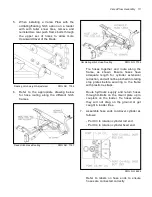
Refer to drawing number 7627. Fasten the
square connector next to the hydraulic quick
couplers. Route the cable along the skid-steer
arm to the pivot point of the arm and secure with
the supplied plastic tie straps. It is especially
important to leave adequate cable at the pivot
point to allow for arm movement.
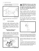
Next, the switch cable needs to be routed into
the cab. Attach the switch to the control arm
using a plastic tie strap as shown in drawing
number 4284.
DWG NO. 4284
Route the third length of the cable to the battery.
Connect the red fused wire ring terminal to the
positive post of the battery and the black wire
ring terminal to the negative post of the battery.
Ensure all wires are away from hot or moving
parts, and secured with plastic ties to prevent
damage.
The wiring on the plow comes preinstalled. The
connectors to the solenoids should be fi rmly
seated. The connectors are interchangeable, as
both solenoids are activated at the same time
when the push button switch is pressed.
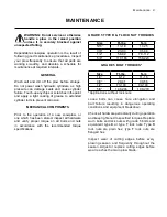
8.
Attach two leveling bars onto the ribs using
provided 5/16 hardware.
DWG NO. 7759
Verify top bar rotates freely on bushing after as-
sembly.
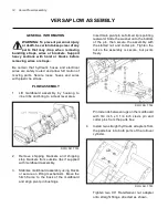
QUICK COUPLERS
Select and install hydraulic quick couplers
and adapter fi ttings on VersaPlow feed lines
according to the size and type (i.e. fl at face or
poppet style) of couplers on customers machine.
Hoses supplied on VersaPlow have 9/16-18
JIC female swivel ends for 9/16-18 JIC male
adapters.
UNIVERSAL CONTROLLER
ELECTRICAL WIRING
Identify the electrical control cable purchased
with the snowplow. It has a square 4-pin
weather pack connector on the fi rst end, two ring
terminals on the second end, and a single push
button switch on the third end.
DWG NO. 7627
14 VersaPlow Assembly


