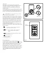
background image

3 SPEED FAN & LIGHT

REMOTE CONTROL

INSTALLATION INSTRUCTIONS

Model: 980014

READ AND SAVE THESE INSTRUCTIONS

INSTALLING THE WALL CONTROL

REMEMBER

  to turn off the power before you begin.

NOTE -

 Secures to any surface or application: flat wall, single gang 

box, multi gang box. 

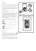
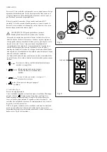
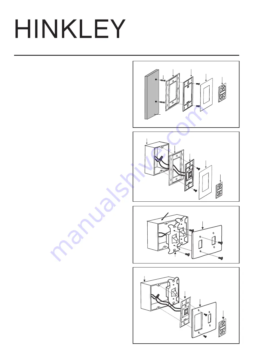
Option 1. Flat Surface Installation

1.   Select a desired location. Use the wall plate to mark the location of 

the mounting holes. Plastic wall anchors or mounting screws are 

needed for this application. (Fig. 1) 

2.   Seat the cradle B into the wall plate. Secure the wall plate to the 

wall using the provided hardware.

3.   Snap the face plate cover onto the wall bracket.

4.   Remote transmitter will be held in place with built in magnets. 

Option 2. For single gang box

1.   Remove the existing wall plate and the old switch from the wall 

outlet box.

2.   Seat the cradle A into the wall plate. (Fig. 2) 

3.   Connect the black lead wires from the switch in the cradle A to the 

black wires in the switch box. Hot input wire to one of the cradle A 

switch leads. Power lead to the fan is connected to the remaining  

switch lead.

4.   Connect the wall plate / cradle A assembly to the wall outlet box  

using the supplied hardware.

5.   Snap the face plate cover onto the wall bracket.

6.   Remote transmitter will be held in place with built in magnets. 

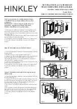
Option 3. Multi Gang Wall Switch Box Installation

1.   Remove the existing wall plate and old switch from the wall outlet 

box. (Fig. 3) 

2.   Connect the black lead wires from the switch in the cradle A to the 

black wires in the switch box. Hot input wire to one of the cradle 

switch leads. Power lead to the fan is connected to the remaining 

switch lead. (Fig. 4)

3.   Attach the cradle A to the wall switch box using the supplied 

hardware.

4.   Attach the multi-gang faceplate to the switch set in the wall outlet 

box. Cradle A of Hinkley switch will fit in any standard decora face 

plate.

5.   Remote transmitter will be held in place with built in magnets.

Fig. 1

Fig. 2

Fig. 3

Fig. 4

Outlet box

Transmitter

Face plate

Wall plate

Cradle A

Outlet box

Face plate

Switch

Outlet box

Transmitter

Face plate

Cradle A

Transmitter

Face plate

Wall plate Cradle B

Wall

Plastic 

anchor

Summary of Contents for 980014

Page 1: ... to one of the cradle A switch leads Power lead to the fan is connected to the remaining switch lead 4 Connect the wall plate cradle A assembly to the wall outlet box using the supplied hardware 5 Snap the face plate cover onto the wall bracket 6 Remote transmitter will be held in place with built in magnets Option 3 Multi Gang Wall Switch Box Installation 1 Remove the existing wall plate and old ...

Page 2: ...sed on instructions above and all controls must be within 30 feet of the fan Fig 5 Fig 6 OPERATION WARNING Chemical Burn Hazard Keep batteries away from children This product contains a lithium button coin cell battery If a new or used lithium button coin cell battery is swallowed or enters the body it can cause severe internal burns and can lead to death in as little as 2 hours Always completely ...

Page 3: ...ble de alimentación del ventilador está conectado al cable del interruptor restante 4 Conecte el ensamblaje de la placa de pared base A a la caja de salida de pared usando los accesorios suministrados 5 Encaje la cubierta de la placa frontal en el soporte de pared 6 El transmisor remoto se mantendrá en su lugar con imanes integrados Opción 3 Instalación de la caja de interruptores de pared de múlt...

Page 4: ...baterías pueden haber sido ingeridas o colocadas dentro de cualquier parte del cuerpo busque atención médica de inmediato Las baterías deben desecharse correctamente incluso manteniéndolas fuera del alcance de los niños Incluso las células usadas pueden causar lesiones EN APAGADA Luz de señal 1 2 3 4 Presione este botón para apagar el ventilador Proceso de emparejamiento Con el ventilador apagado ...

Page 5: ... berceau A Le fil d alimentation du ventilateur est connecté au fil de l interrupteur restant 4 Connectez l ensemble plaque murale berceau A à la boîte de sortie murale à l aide du matériel fourni 5 Enclenchez le couvercle de la plaque frontale sur le support mural 6 L émetteur à distance sera maintenu en place avec des aimants intégrés Option 3 Installation d un boîtier d interrupteur mural multi...

Page 6: ...placées à l intérieur de n importe quelle partie du corps consultez immédiatement un médecin Les batteries doivent être éliminées correctement notamment en les gardant hors de portée des enfants Même les cellules utilisées peuvent causer des blessures SUR DÉSACTIVÉ Feu de signalisation 1 2 3 bouton Appuyez sur le bouton pour allumer et régler la vitesse du ventilateur de 1 à 3 4 bouton Appuyez sur...

Reviews: