background image

WARNING:

Read and follow these instructions carefully and be mindful of all warnings shown throughout.

©2019 Hinkley Lighting, Inc. 

|

 hinkley.com 

|


01

TABLE OF CONTENTS

02

GENERAL INSTALLATION & OPERATING 

INSTRUCTIONS

03

IMPORTANT SAFETY PRECAUTIONS

03

TOOLS & MATERIALS REQUIRED

04

UNPACKING YOUR FAN

05

PREPARATION

05

INSTALLING THE HANGING BRACKET

06

INSTALLING THE FAN WITH A DOWNROD CONFIGURATION

08

ELECTRICAL CONNECTIONS

09

FINISHING THE INSTALLATION

10

BLADE ATTACHMENT

11

INSTALLATION OF REMOVABLE SWITCH HOUSING

12

OPERATION

13

CARE AND CLEANING

13

TROUBLESHOOTING

14

ENERGY GUIDE

14

SPECIFICATIONS

14

SMART BY BOND

Summary of Contents for HIGHLAND

Page 1: ...52 HIGHLAND CEILING FAN INSTRUCTION MANUAL INDOOR OUTDOOR FAN WET ...

Page 2: ... installation and operation of this fan It has been designed to make the installation process as easy as possible If you are unfamiliar or uncomfortable with wiring please contact a qualified electrician If you need additional assistance or have any questions please reach out to us For warranty information visit hinkley com SERVICE HINKLEY COM 800 HINKLEY LET S SEE THAT HINKLEY STYLE HINKLEY HINKL...

Page 3: ...S 03 IMPORTANT SAFETY PRECAUTIONS 03 TOOLS MATERIALS REQUIRED 04 UNPACKING YOUR FAN 05 PREPARATION 05 INSTALLING THE HANGING BRACKET 06 INSTALLING THE FAN WITH A DOWNROD CONFIGURATION 08 ELECTRICAL CONNECTIONS 09 FINISHING THE INSTALLATION 10 BLADE ATTACHMENT 11 INSTALLATION OF REMOVABLE SWITCH HOUSING 12 OPERATION 13 CARE AND CLEANING 13 TROUBLESHOOTING 14 ENERGY GUIDE 14 SPECIFICATIONS 14 SMART ...

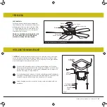
Page 4: ...not allow rotating fan blades to come in contact with any object Blades should be at least 7 feet from floor Blades should be attached after motor housing is hung and in place Fan motor housing should be kept in the carton until ready to be installed to protect its finish If you are installing more than one ceiling fan make sure that you do not mix fan blade sets as each blade is part of a weighted ...

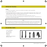
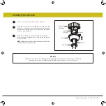
Page 5: ...03 Disconnect power by removing fuse or turning off circuit breaker before installing the fan and or optional lighting Support directly from building structure To reduce the risk of fire electric shock or personal injury mount to outlet box marked acceptable for fan support and use mounting screws provided with the outlet box Most outlet boxes commonly used for the support of lighting fixtures are no...

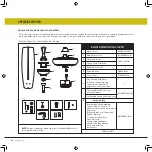
Page 6: ...KAGECONTENT 1 Blade Set of 5 2 Blade Arm Set of 5 3 Hanging Bracket 4 5 Canopy with Trim Ring 6 Ball Moisture Cover 7 8 9 Downrod Asm Yoke Cover Fan Housing with Motor Remove rubber shipping supports around motor if applicable Save the screws Detachable Switch Housing Cover Detachable Switch Housing w Wiring Harness 10 10 Hardware Bag Bracket Mounting Hardware wood screws screws lock washers star ...

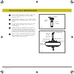
Page 7: ...y is turned off at the main power box before wiring All wiring must be in accordance with National and Local Electrical Codes and the ceiling fan must be grounded as a precaution against possible electric shock Locate ceiling joist where fan is to be mounted being sure location agrees with the requirements in the minimum clearance section of this guide Wood joists must be sound and of adequate size...

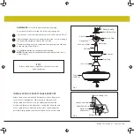
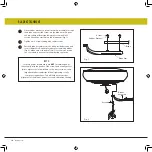
Page 8: ...he motor assembly Fig 2 Carefully feed the electrical lead wires and safety cable from the fan through the downrod Thread downrod into coupler until holes align Insert downrod pin through holes in mounting collar and downrod clip cotter pin through small hole in end of downrod pin to hold downrod in place Tighten security screws against downrod using a large flat blade screwdriver to ensure a tigh...

Page 9: ...ig 3 Lift ball downrod fan into hanger bracket opening NOTE The tab opposite hanger bracket opening should fit in slot on ball Fig 4 6 7 8 9 NOTE 6 feet of lead wire is supplied on the fan for use with longer downrods Trim Ring Safety Cable Fig 4 Attach the wood screw and the flat washer to the ceiling joist as shown do not fully tighten Slide the cable clamp onto the safety cable from the fan Loop ...

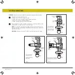
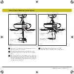
Page 10: ...ot power for light kit Green ground wire on bracket or downrod If fan and light are to be connected to the same circuit black and blue wires can both be connected to house circuit black wire NOTE The other end of the blue wire light circuit is in the switch housing with a wire nut and label for light kit attachment The white wire common for light kit is also there WARNING If light kit is not used ...

Page 11: ...he circular hole on canopy with the remaining hole on the mounting bracket secure by tightening the two set screws NOTE Adjust the canopy screws as necessary until the canopy and trim ring are snug Make sure the hook on the hanging bracket properly sits in the groove in the hanger ball before attaching the canopy to the bracket by turning the housing until it drops into place 2021 Hinkley Lighting...

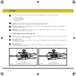
Page 12: ...at procedure for remaining blades Fig 2 Make sure screws are TIGHT Loose motor screws can contribute to unnecessary hum during operation Fig 1 Fig 2 Screw Blade Arm Blade NOTE Cordless power screwdrivers are NOT recommended as they usually strip the heads of the screws and usually will not fully compress the lock washers on the motor screws Use a large flat blade screwdriver for final tightening t...

Page 13: ...hableSwitch housing close to the mounting hub and push the square wire connectors together Fig 1 Place the key holes on the DetachableSwitch housing over the 2 screws previously loosened from the adapter plate turn light kit until it locks in place at the narrow section of the key holes Secure by tightening the 2 screws previously loosened and the one previously removed Fig 1 1 Install the Detacha...

Page 14: ...y be sure that fan is switched to off and blades have stopped moving completely before attempting to change direction of rotation Summer Mode and Winter Mode Operation The reverse switch is located on the surface of the switch housing Slide the switch to the right for winter mode operation Slide the switch to the left for summer mode operation Summer Mode forward A DOWNWARD airflow creates a cooling...

Page 15: ... are well held in the sockets if a light kit is used 5 Check that the canopy is firmly attached to hanging bracket and not vibrating against ceiling 1 Check that all blades are firmly screwed into blade arms Check that all blade arms are firmly secure to the motor 2 Check to make sure that light kit if present is firmly attached to switch housing and that all glassware and shades are fastened properly...

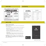
Page 16: ...rcuit through the wall control Maximum of 12 fans can operate on a circuit through an on off switch or breaker when utilizing the app for the fan control without the wall control in the circuit AVERAGE PERFORMANCE AND ENERGY INFORMATION ftc gov energy The higher the airflow the more air the fan will move Airflow Efficiency 95 Cubic Feet Per Minute Per Watt Airflow 3 516 Cubic Feet Per Minute Based ...

Page 17: ...UCTS THAT ENHANCE YOUR SPACE WITH COMFORT PURPOSE AND STYLE AS A FAMILY COMPANY WE ARE COMMITTED TO DESIGN PERFORMANCE AND QUALITY AND WHAT S IMPORTANT TO YOU IS PARAMOUNT TO US FOR A COMPLETE ASSORTMENT OF OUR PRODUCTS AND SOURCE BOOKS VISIT HINKLEY COM ...

Page 18: ...GLOBAL HEADQUARTERS 33000 Pin Oak Parkway Avon Lake Ohio 44012 T 440 653 5500 F 440 653 5555 hinkley com ...

Page 19: ...MANUAL DE INSTRUCCIONES PARA VENTILADORES DE TECHO 52 HIGHLAND VENTILADOR INTERIOR EXTERIOR WET ...

Page 20: ...ado Si necesita asistencia adicional o tiene alguna pregunta comuníquese con nosotros Para obtener información sobre la garantía visite hinkley com SERVICE HINKLEY COM 800 HINKLEY VAMOS A ESE ESTILO HINKLEY HINKLEY HINKLEYSTYLE QUEREMOS QUE AMES A TU NUEVO VENTILADOR ASÍ QUE ESTAMOS AQUÍ SI TIENE UNA PREGUNTA NECESITA AYUDA O QUIERE HABLAR SOBRE NUESTROS PRODUCTOS ENVÍE SUGERENCIAS NUESTRO CAMINO ...

Page 21: ...NES PRECAUCIONES DE SEGURIDAD IMPORTANTES HERRAMIENTAS Y MATERIALES REQUERIDOS DESEMBALAJE SU VENTILADOR PREPARACIÓN INSTALACIÓN DEL SOPORTE COLGANTE INSTALACIÓN DEL VENTILADOR CON UNA CONFIGURACIÓN DE VARILLA ABAJO CONEXIONES ELÉCTRICAS TERMINANDO LA INSTALACIÓN 10 11 12 13 13 14 14 14 ACCESORIO DE HOJA INSTALACIÓN DE LA CARCASA DEL INTERRUPTOR EXTRAÍBLE OPERACIÓN CUIDADO Y LIMPIEZA SOLUCIÓN DE P...

Page 22: ...aspas del ventilador giratorio entren en contacto con ningún objeto Las cuchillas deben estar al menos a 7 pies del piso Las cuchillas deben colocarse después de colgar y colocar la carcasa del motor La carcasa del motor del ventilador debe guardarse en la caja hasta que esté lista para ser instalada para proteger su acabado Si está instalando más de un ventilador de techo asegúrese de no mezclar ...

Page 23: ...el ventilador y o la iluminación opcional Soporte directamente desde la estructura del edificio Para reducir el riesgo de incendio descarga eléctrica o lesiones personales móntelo en la caja de salida marcada como aceptable para soporte del ventilador y use los tornillos de montaje que se proporcionan con la caja de salida La mayoría de las cajas de distribución que se utilizan comúnmente para el ...

Page 24: ...colgar 4 5 Marquesina con anillo embellecedor 6 Cubierta de humedad de bola 7 8 9 Asm de varilla Cubierta del yugo Carcasa del ventilador con motor Quite los soportes de goma para transporte alrededor del motor si corresponde Guarde los tornillos Cubierta de la carcasa del interruptor desmontable Carcasa de interruptor desmontable con arnés de cableado 10 10 Bolsa de hardware Hardware de montaje d...

Page 25: ...urándose de que la ubicación coincida con los requisitos de la sección de espacio libre mínimo de esta guía Las vigas de madera deben ser sólidas y de tamaño adecuado para soportar 35 libras vea la página 2 elementos 3 y 4 Si aún no está presente monte una caja de salida listada por UL marcada como adecuada para soporte de ventilador siguiendo las instrucciones proporcionadas con la caja de salida...

Page 26: ...l acoplamiento en la parte superior del conjunto del motor Figura 2 Pase con cuidado los cables eléctricos y el cable de seguridad del ventilador a través de la varilla Enrosque la varilla en el acoplador hasta que los agujeros se alineen Inserte el pasador de la varilla a través de los orificios en el collar de montaje y la varilla Sujete el pasador de chaveta a través del pequeño orificio en el ...

Page 27: ...e suspensión NOTA La pestaña opuesta a la abertura del soporte de suspensión debe encajar en la ranura de la bola Figura 4 6 7 8 9 NOTA Se suministran 6 pies de cable conductor en el ventilador para usar con varillas más largas Fig 4 INSTALACIÓN DE SOPORTE DE CABLE DE SEGURIDAD Fije el tornillo para madera y la arandela plana a la viga del techo como se muestra no apriete completamente Deslice la ...

Page 28: ...ara el kit de luz también está allí ADVERTENCIA Si no se utiliza el kit de luces NO conecte el cable azul en el techo Fig 1 Fig 3 1 2 Fig 2 Ventilador controlado por cadena de tracción en el ventilador Luz controlada por interruptor de pared la lámpara la lámpara la lámpara Líneas eléctricas 120 V Líneas eléctricas 120 V Líneas eléctricas 120 V Ventilador controlado por cadena de tracción en el ve...

Page 29: ...ra Alinee el orificio circular en el dosel con el orificio restante en el soporte de montaje asegure apretando los dos tornillos de fijación NOTA Ajuste los tornillos de la capota según sea necesario hasta que la capota y el anillo de moldura estén ajustados ADVERTENCIA Asegúrese de que el gancho del soporte para colgar se asiente correctamente en la ranura de la bola de suspensión antes de sujeta...

Page 30: ...se de que los tornillos estén APRETADOS Los tornillos del motor flojos pueden contribuir a un zumbido innecesario durante el funcionamiento Fig 1 Fig 2 Tornillo Brazo de hoja Espada NOTA NO se recomiendan los destornilladores eléctricos inalámbricos ya que generalmente pelan las cabezas de los tornillos y por lo general no comprimen completamente las arandelas de seguridad de los tornillos del mot...

Page 31: ...de montaje y junte los conectores de cables cuadrados Figura 1 Coloque los orificios de la cerradura en la carcasa del Interruptor Desmontable sobre los 2 tornillos previamente aflojados de la placa adaptadora gire el juego de luces hasta que encaje en su lugar en la sección estrecha de los orificios de la llave Asegure apretando los 2 tornillos previamente aflojados y el que previamente quitó Fig...

Page 32: ... asegúrese de que el ventilador esté apagado y las aspas hayan dejado de moverse por completo antes de intentar cambiar la dirección de rotación Funcionamiento en modo verano y modo invierno El interruptor de marcha atrás se encuentra en la superficie de la carcasa del interruptor Deslice el interruptor hacia la derecha para operar en modo invierno Deslice el interruptor hacia la izquierda para el...

Page 33: ...os y que las bombillas estén bien sujetas en los casquillos si se usa un juego de luces 5 Verifique que el dosel esté firmemente sujeto al soporte colgante y que no vibre contra el techo 1 Verifique que todas las hojas estén bien atornilladas en los brazos de las hojas Verifique que todos los brazos de la cuchilla estén firmemente sujetos al motor 2 Verifique que el juego de luces si lo hay esté b...

Page 34: ...r su cuenta También puede iniciar sesión con su cuenta de Facebook o Google Luego configure una conexión WiFi Necesitará el SSID y la contraseña de WiFi para la red a la que desea conectarse Recibirá un mensaje para elegir el acabado de su ventilador y nombrar su dispositivo de ventilador La aplicación lo guiará a través de la pantalla principal y le mostrará cómo cambiar las velocidades de los ve...

Page 35: ...QUE MEJORAN SU ESPACIO CON COMODIDAD PROPÓSITO Y ESTILO COMO EMPRESA FAMILIAR ESTAMOS COMPROMETIDOS CON EL DISEÑO EL RENDIMIENTO Y LA CALIDAD Y LO QUE ES IMPORTANTE PARA USTED ES PARAMOUNT PARA NOSOTROS PARA UN SURTIDO COMPLETO DE NUESTROS PRODUCTOS Y FUENTES DE LIBROS VISITA HINKLEY COM ...

Page 36: ...GLOBAL HEADQUARTERS 33000 Pin Oak Parkway Avon Lake Ohio 44012 T 440 653 5500 F 440 653 5555 hinkley com ...

Page 37: ...MANUEL D UTILISATION DU VENTILATEUR DE PLAFOND 52 HIGHLAND VENTILATEUR INTÉRIEUR EXTÉRIEUR WET ...

Page 38: ... Si vous avez besoin d aide supplémentaire ou avez des questions n hésitez pas à nous contacter Pour des informations sur la garantie visitez hinkley com SERVICE HINKLEY COM 800 HINKLEY LET S SEE THAT HINKLEY STYLE HINKLEY HINKLEYSTYLE NOUS VOULONS VOUS AIMER VOTRE NOUVEAU FAN NOUS SOMMES ICI SI VOUS AVEZ UNE QUESTION BESOIN D UNE AIDE OU VOULEZ CHAT SUR NOS PRODUITS ENVOYER DES SUGGESTIONS NOTRE ...

Page 39: ...ON INSTALLATION DU SUPPORT DE SUSPENSION INSTALLATION DU VENTILATEUR AVEC UNE CONFIGURATION DOWNROD CONNECTIONS ELECTRIQUES FIN DE L INSTALLATION 10 11 12 13 13 14 14 14 FIXATION DE LA LAME INSTALLATION DU BOÎTIER DE COMMUTATEUR AMOVIBLE OPÉRATION ENTRETIEN ET NETTOYAGE DÉPANNAGE GUIDE DE L ÉNERGIE CARACTÉRISTIQUES SMART BY BOND ATTENTION Lisez et suivez attentivement ces instructions et tenez com...

Page 40: ...trer en contact avec un objet Les lames doivent être à au moins 7 pieds du sol Les lames doivent être fixées une fois le carter du moteur suspendu et en place Le boîtier du moteur du ventilateur doit être conservé dans le carton jusqu à ce qu il soit prêt à être installé pour protéger sa fi nition Si vous installez plusieurs ventilateurs de plafond assurez vous de ne pas mélanger les ensembles de p...

Page 41: ...sjoncteur avant d installer le ventilateur et ou l éclairage en option Support directement depuis la structure du bâtiment Pour réduire les risques d incendie d électrocution ou de blessures montez sur la boîte de sortie marquée acceptable pour le support du ventilateur et utilisez les vis de montage fournies avec la boîte de sortie La plupart des boîtiers de sortie couramment utilisés pour le sup...

Page 42: ...port vis à bois vis rondelles de blocage rondelles en étoile rondelles plates écrous de fil Vis de lame à bras de lame et rondelles en caoutchouc Vis avec rondelles de blocage Encastré 3 Matériel de câble de sécurité vis à bois rondelle plate Tirez la chaîne avec Fob Kit d équilibre XX FINITION DU VENTILATEUR YC902672Fxx x SWH904152Fxx W MH904152Fxx W DR94014Fxx x CA902672Fxx BLI904152Fxx W BL9041...

Page 43: ...allé en vous assurant que l emplacement est conforme aux exigences de la section de dégagement minimum de ce guide Les solives de bois doivent être solides et de taille adéquate pour supporter 35 livres voir page 2 éléments 3 et 4 S il n est pas déjà présent montez une boîte de sortie homologuée UL marquée approprié pour le support du ventilateur en suivant les instructions fournies avec la boîte ...

Page 44: ...upille d attelage et le clip de retenue de l accouplement sur le dessus de l assemblage du moteur Fig 2 Faites passer soigneusement les fils électriques et le câble de sécurité du ventilateur à travers la tige de descente Enfilez la tige descendante dans le coupleur jusqu à ce que les trous s alignent Insérez la goupille de la tige descendante dans les trous du collier de montage et de la tige des...

Page 45: ...entilateur dans l ouverture du support de suspension REMARQUE La languette opposée à l ouverture du support de suspension doit s insérer dans la fente de la bille Fig 4 6 7 8 9 REMARQUE 6 pieds de fil de plomb sont fournis sur le ventilateur pour une utilisation avec des tiges de descente plus longues Anneau de garniture INSTALLATION DU SUPPORT DE CÂBLE DE SÉCURITÉ Fixez la vis à bois et la rondel...

Page 46: ...ion du kit d éclairage Le fil blanc commun pour le kit d éclairage est également là AVERTISSEMENT si le kit d éclairage n est pas utilisé NE PAS connecter de fil bleu au plafond Fig 1 Fig 3 1 2 Fig 2 Ventilateur contrôlé par une chaîne de traction sur le ventilateur Contrôle de la lumière par interrupteur mural Ventilateur contrôlé par une chaîne de traction sur le ventilateur Contrôle de la lumiè...

Page 47: ...é Alignez le trou circulaire sur l auvent avec le trou restant sur le support de montage fixez en serrant les deux vis de réglage REMARQUE Ajustez les vis de l auvent au besoin jusqu à ce que l auvent et l anneau de garniture soient bien serrés ATTENTION Assurez vous que le crochet du support de suspension se trouve correctement dans la rainure de la boule de suspension avant de fixer la verrière ...

Page 48: ...vous que les vis sont SERRÉES Des vis de moteur desserrées peuvent contribuer à un bourdonnement inutile pendant le fonctionnement Fig 1 Fig 2 Visser Bras de lame Lame REMARQUE Les tournevis électriques sans fil ne sont PAS recommandés car ils dénudent généralement les têtes des vis et ne compressent généralement pas complètement les rondelles de blocage sur les vis du moteur Utilisez un gros tour...

Page 49: ...s du moyeu de montage et poussez les connecteurs de fils carrés ensemble Fig 1 Placez les trous de clé sur le boîtier DetachableSwitch sur les 2 vis précédemment desserrées de la plaque d adaptation tournez le kit d éclairage jusqu à ce qu il se verrouille en place dans la section étroite des trous de clé Fixez en serrant les 2 vis précédemment desserrées et celle précédemment retirée Fig 1 1 Inst...

Page 50: ...est pas coincé entre les positions avant et arrière IMPORTANT pour éviter tout dommage ou blessure assurez vous que le ventilateur est éteint et que les pales ont complètement cessé de bouger avant de tenter de changer le sens de rotation Fonctionnement en mode été et en mode hiver L interrupteur de marche arrière est situé sur la surface du boîtier de l interrupteur Faites glisser l interrupteur ...

Page 51: ...bien serrée et que les ampoules sont bien tenues dans les douilles si un kit d éclairage est utilisé 5 Vérifiez que l auvent est solidement fixé au support de suspension et ne vibre pas contre le plafond 1 Vérifiez que toutes les lames sont fermement vissées dans les bras de lame Vérifiez que tous les bras de lame sont solidement fixés au moteur 2 Assurez vous que le kit d éclairage le cas échéant...

Page 52: ... invité à choisir la finition de votre ventilateur et à nommer votre périphérique de ventilateur L application vous guidera à travers l écran principal et vous montrera comment modifier la vitesse des ventilateurs atténuer la lumière régler les minuteries ou utiliser le mode brise GUIDE ÉNERGÉTIQUE CARACTÉRISTIQUES PERFORMANCE MOYENNE ET INFORMATIONS ÉNERGÉTIQUES SPÉCIFICATIONS DE PERFORMANCE Débi...

Page 53: ...ÉLIORENT VOTRE ESPACE AVEC CONFORT OBJECTIF ET STYLE EN TANT QU ENTREPRISE FAMILIALE NOUS NOUS ENGAGEONS À CONCEVOIR PERFORMANCE ET QUALITÉ ET CE QUI EST IMPORTANT POUR VOUS EST PARAMOUNT POUR NOUS POUR UN ASSORTIMENT COMPLET DE NOS PRODUITS ET LIVRES DE SOURCE VISITEZ HINKLEY COM ...

Page 54: ...GLOBAL HEADQUARTERS 33000 Pin Oak Parkway Avon Lake Ohio 44012 T 440 653 5500 F 440 653 5555 hinkley com ...

Reviews: