


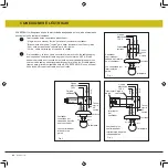
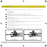


ACCESORIO DE HOJA
1
2
3
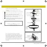
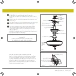
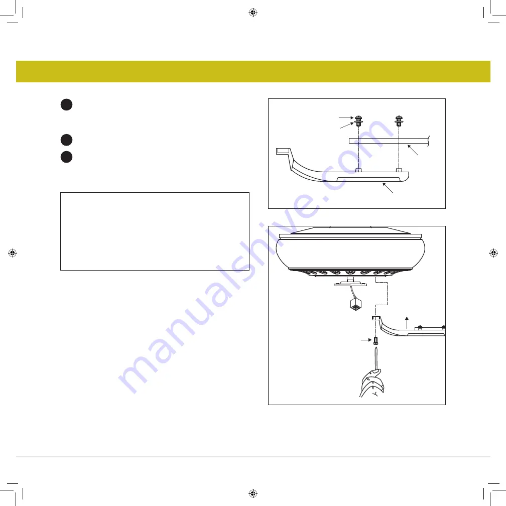
Coloque la arandela de goma en el tornillo. Inserte este conjunto a
través de la hoja y coloque el tornillo en el brazo de la hoja. Repita
este procedimiento sin apretar el tornillo hasta que los 3 tornillos se
hayan introducido en el brazo de la hoja (Fig. 1).
Apriete cada tornillo comenzando por el tornillo central.
Fije el conjunto de cuchillas al motor con los tornillos y las arandelas
de seguridad provistos. Repita el procedimiento para las hojas
restantes (Fig. 2). ¡Asegúrese de que los tornillos estén
APRETADOS! Los tornillos del motor flojos pueden contribuir a un
zumbido innecesario durante el funcionamiento
Fig. 1
Fig. 2
Tornillo
Brazo de hoja
Espada
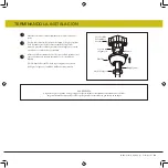
NOTA:
NO se recomiendan los destornilladores eléctricos inalámbricos, ya
que generalmente pelan las cabezas de los tornillos y, por lo general,
no comprimen completamente las arandelas de seguridad de los
tornillos del motor. Utilice un destornillador grande de hoja plana
para un ajuste final y comprimir completamente las arandelas. Esto
ayudará a garantizar la alineación adecuada de las cuchillas y un
funcionamiento sin ruidos y sin oscilaciones.
.
Empulgueras
Ensamblaje de
cuchillas
10
|
hinkley.com
Lavadora de caucho
r


