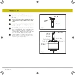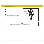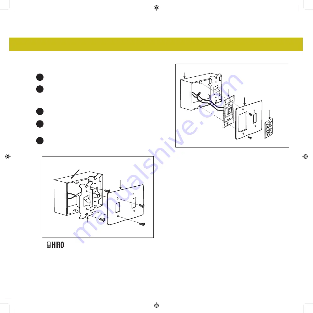
Fig. 3
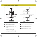
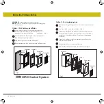
Remove the existing wall plate and old switch from the wall
outlet box. (Fig. 3)
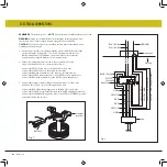
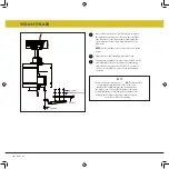
Connect the black lead wires from the switch in the cradle A
to the black wires in the switch box. Hot input wire to one of
the cradle switch leads. Power lead to the fan is connected
to the remaining switch lead. (Fig. 4)
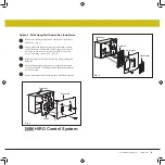
Attach the cradle A to the wall switch box using the supplied
hardware.
Attach the multi-gang faceplate to the switch set in the wall
outlet box. Cradle A of Hinkley switch will fit in any standard
decora face plate.
Remote transmitter will be held in place with built in magnets.
1
2
3
4
5
Option 3. Multi Gang Wall Switch Box Installation
©2019 Hinkley Lighting, Inc.
|
hinkley.com
|
13
Fig. 4
Outlet box
Face plate
Switch
Outlet box
Transmitter
Face plate
Cradle A
HIRO Control System

