


©2019 Hinkley Lighting, Inc.
|
hinkley.com
|
11
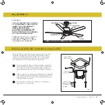
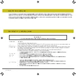
,167$/$1'2(/&21-8172'(/('</$&8%,(57$/,*(5$
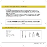
1
2
3
4
5
5
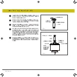
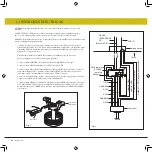
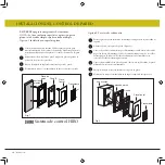
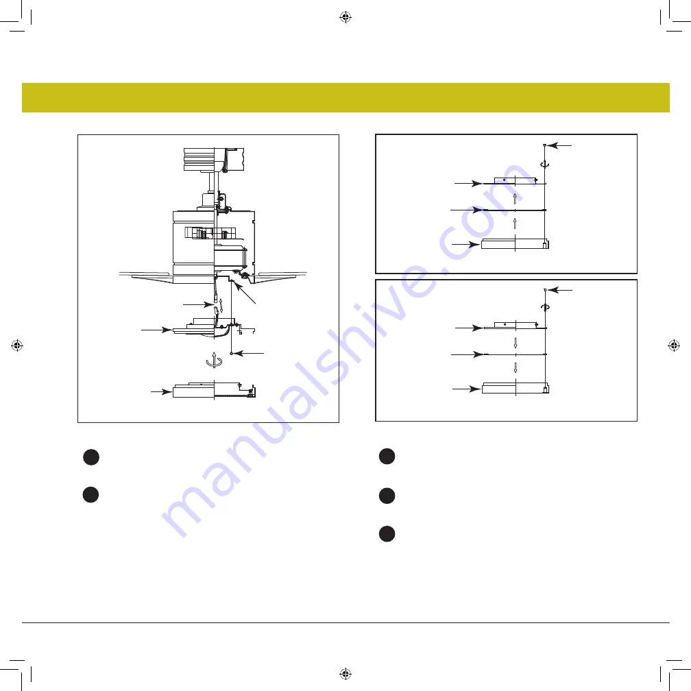
5HWLUHXQRGHORVWUHVWRUQLOORVHQHOFXERGHPRQWDMH
XELFDGRHQHOPRWRUGHOYHQWLODGRU)LJXUD
0LHQWUDVVRVWLHQHHOFRQMXQWRGH/('GHEDMRGHVX
YHQWLODGRUUHDOLFHODVFRQH[LRQHVGHHQFKXIHSRODUL]DGDV
)LJ
-
URMRDEODQFR
-
1HJURDQHJUR
127$
6L QR SODQHD LQVWDODU HO NLW GH OX] /(' FRQ VX
YHQWLODGRUHQHVWHPRPHQWRQRUHDOLFHODVFRQH[LRQHVGHORV
FDEOHV
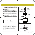
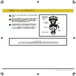
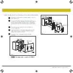
5HWLUHORVWRUQLOORV\VDTXHODSODFDGHYLGULRGHODFXELHUWDGH
ODOX])LJOXHJRILMHODFXELHUWDGHPHWDODODFXELHUWDGH
OD OX] % \ OD FXELHUWD GH OD OX] $ FRQ ORV WRUQLOORV SURYLVWRV
)LJ
Fig. 1
&XERGHPRQWDMH
SDUWHLQIHULRUGHO
PRWRU
)
&RQHFWRUHVGH
DODPEUH
Fig. 2
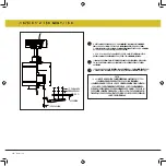
Fig. 3
&RORTXHODVFRQH[LRQHVSHUIHFWDPHQWHHQHOHQVDPEODMHGHO/('
FRORTXHHOHQVDPEODMHGHO/('HQHOFXERGHPRQWDMHFRQWRUQLOORV
SURYLVWRV)LJXUD
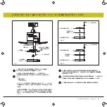
/HYDQWHODFXELHUWDGHODOX]FRQWUDHOHQVDPEODMHGHO/('\JLUHHQHO
VHQWLGRGHODVDJXMDVGHOUHORMKDVWDTXHTXHGHDMXVWDGD)LJXUD
5HVWDXUHODHQHUJtD\VXNLWGHOXFHVHVWDUiOLVWRSDUDIXQFLRQDU
&XELHUWD
OLJHUD
0RQWDMH
/('
(PSXOJXHUDV
(PSXOJXHUDV
7DEOHURGH
YLGULR
&XELHUWDGHOX]$
&XELHUWDGHOX]$
&XELHUWDGHOX]%
&XELHUWDGHOX]%
(PSXOJXHUDV
&XELHUWD
PHWiOLFD


