HYBRID/TROUBLE SHOOTING
3–626
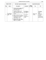
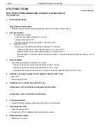
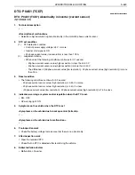
DTC: P0A51 (TCD6)
EN01H03ZZZ030602004048
DTC: P0A51 (TCD6) Abnormality in inverter (current sensor)
INFORMATION
1.
Technical description
•
–
<Description of malfunction>
•
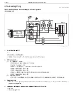
Detected a high resolution signal abnormality in the motor V-phase current sensor.
2.
DTC set condition
(1)
DTC detection condition
•
Control power supply voltage is 8 V or more.
•
Inverter start signal is ON.
•
V-phase current value (low resolution) is less than 175 A.
(2)
Judgement criteria
•
When one of the following conditions continues for 0.1 second:
- V-phase current sensor value (high resolution) is less than 0.30 V.
- V-phase current sensor value (high resolution) is more than 4.40 V.
- The difference of (V-phase current value [low resolution] - V-phase current value [high resolution]) is more
than 75 A.
3.
Reset condition
•
The following conditions continue for 0.2 second:
- V-phase current sensor value (high resolution) is 0.30 V or more.
- V-phase current sensor value (high resolution) is 4.40 V or less.
- (V-phase current value [low resolution] - V-phase current value [high resolution]) is 75 A or less.
4.
Indication, warning or system control regulation when the DTC is set.
•
MIL: OFF
•
HV warning light: ON
5.
Symptoms on the vehicle when the DTC is set
<Symptoms on the vehicle due to backup control (fail safe)>
•
–
<Symptoms on the vehicle due to malfunction>
•
–
6.
Pre-inspection work
•
Check the battery voltage to make sure that there is no abnormality.
7.
After-inspection work
•
Clear the recorded DTC.
•
Check that no DTC is detected after test-driving the vehicle.
8.
Estimated failure factors
•
Malfunction of inverter


