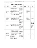
HYBRID/TROUBLE SHOOTING
3–327
CHECKLIST: P324B (TC62)
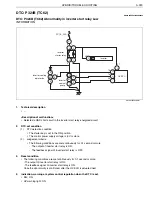
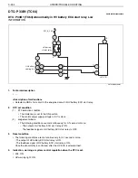
P324B (TC62)
Abnormality in inverter start relay Low
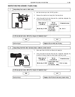
Inspection Procedure
Step
Action
Description
Judgement
Check
(Yes/No)
Yes
No
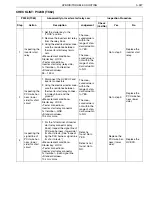
1
Inspecting the
inverter start
relay
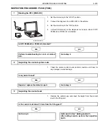
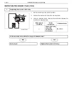
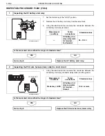
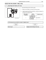
1. Set the starter key to the
"LOCK" position.
2. Remove the inverter start relay
from the relay block.
3. Using the electrical tester, mea-
sure the resistance between
the inverter start relay termi-
nals.
<Measurement conditions>
Starter key: LOCK
<Tester connections>
Inverter start relay (relay side)
1st terminal
–
2nd terminal
<Standard values>
95
–
125
The mea-
sured value is
within the
range of stan-
dard value: Go
to YES.
The mea-
sured value is
not within the
range of stan-
dard value: Go
to NO.
Go to step 2.
Replace the
inverter start
relay.
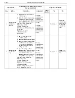
2
Inspecting the
PCU wire har-
ness (lower
side) for short
circuit
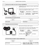
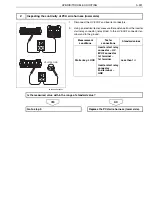
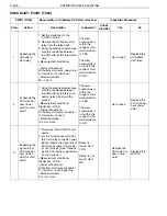
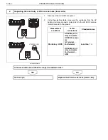
1. Disconnect the HV ECU2 and
inverter connectors.
2. Using the electrical tester, mea-
sure the resistance between
the inverter start relay connec-
tor (relay block) and the
ground.
<Measurement conditions>
Starter key: LOCK
<Tester connections>
Inverter start relay connector
1st terminal
–
GND
<Standard values>
10 k
or more
The mea-
sured value is
within the
range of stan-
dard value: Go
to YES.
The mea-
sured value is
not within the
range of stan-
dard value: Go
to NO.
Go to step 3.
Replace the
PCU wire har-
ness (lower
side).
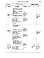
3
Inspecting the
signal line of
PCU wire har-
ness (lower
side) for short
circuit
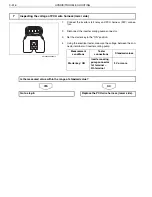
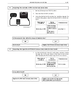
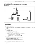
1. For the 1st terminal of inverter
start relay connector (relay
block), inspect the signal line of
PCU wire harness (lower side)
for short circuit. (See "Inspect-
ing the PCU harness signal line
for short circuit.")
<Measurement conditions>
Starter key: LOCK
<Tester connections>
Inverter start relay connector
1st terminal
–
Each signal line
<Standard values>
10 k
or more
Defect is
found: Go to
YES.
Defect is not
found: Go to
NO.
Replace the
PCU wire har-
ness (lower
side).
Replace the
HV ECU.

