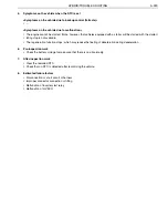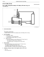
HYBRID/TROUBLE SHOOTING
3–331
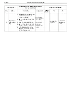
1.
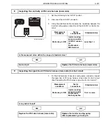
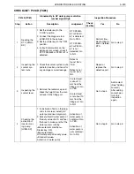
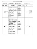
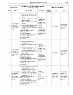
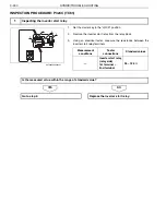
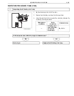
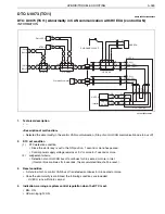
Disconnect the HV ECU2 and inverter connectors.
2.
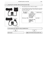
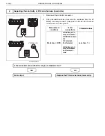
Using an electrical tester, measure the resistance from the inverter
start relay connector (relay block) to the HV ECU2 connector ter-
minal and to the ground.
NO
YES
2
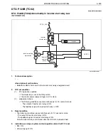
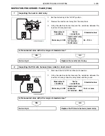
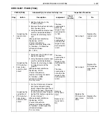
Inspecting the continuity of PCU wire harness (lower side)
VEHICLE GND
SHTS03ZZZ0300222
Measurement
conditions
Tester
connections
Standard values
Starter key: LOCK
Inverter start relay
connector
–
HV
ECU2 connector
1st terminal
–
1st terminal
Inverter start relay
connector
2nd terminal
–
GND
Less than 1
Is the measured value within the range of standard value?
Go to step 3.
Replace the PCU wire harness (lower side).

