HYBRID/TROUBLE SHOOTING
3–582
1.
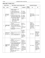
Connect all the connectors that have been disconnected.
2.
Set the starter key to the "ON" position.
3.
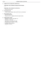
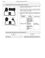
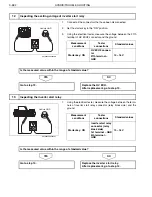
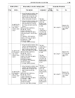
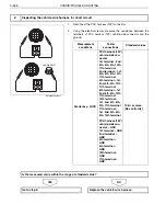
Using the electrical tester, measure the voltage between the 27th
terminal of HV ECU2 connector and the ground.
NO
YES
1.
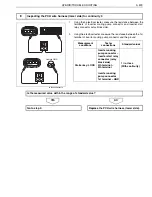
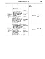
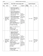
Using the electrical tester, measure the voltage between the termi-
nals of inverter start relay connector (relay block side) and the
ground.
NO
YES
12
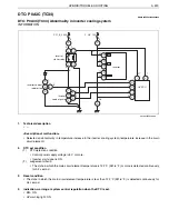
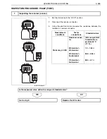
Inspecting the exciting voltage of inverter start relay
Vehicle GND
SHTS03ZZZ0300380
Measurement
conditions
Tester
connections
Standard values
Starter key: ON
HV ECU2 connec-
tor
27th terminal
–
GND
10
–
16 V
Is the measured value within the range of standard value?
Go to step 13.
Replace the HV ECU.
After replacement, go to step 13.
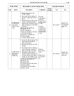
13
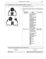
Inspecting the inverter start relay
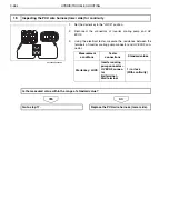
Vehicle GND
SHTS03ZZZ0300381
Measurement
conditions
Tester
connections
Standard values
Starter key: ON
Inverter start relay
connector (relay
block side)
1st terminal
–
GND
5th terminal
–
GND
10
–
16 V
Is the measured value within the range of standard value?
Go to step 14.
Replace the inverter start relay.
After replacement, go to step 14.

