HYBRID/TROUBLE SHOOTING
3–641
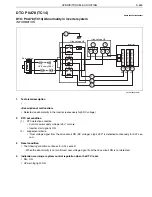
CHECKLIST: P0A78 (TC13)
P0A78 (TC13)
Abnormality in inverter system
Inspection Procedure
Step
Action
Description
Judgement
Check
(Yes/No)
Yes
No
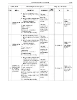
1
Inspecting the
HV battery
ECU [HINO-
DX]
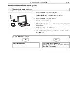
1. Set the starter key to the
"LOCK" position.
2. Connect the diagnosis tool
(HINO-DX) to the vehicle.
3. Set the starter key to the "ON"
position.
4. In [Fault Information] on the
diagnosis tool screen, check if
DTC P0A95 related to the HV
battery line is detected.
DTC P0A95 is
detected: Go
to YES.
DTC P0A95 is
not detected:
Go to NO.
Perform trou-
bleshooting for
each of related
DTC.
Go to step 2.
2
Reading the
DTC [HINO-
DX]
1. In [Fault Information] on the
diagnosis tool screen, check if
any of the following DTC other
than P0A78-13 is detected:
•
P0ADC, P0ADB, P0AE7,
P0AE0, P0AE6, P0ADF
DTC other
than P0A78-
13 is detected:
Go to YES.
DTC other
than P0A78-
13 is not
detected: Go
to NO.
Perform trou-
bleshooting for
each of related
DTC.
Go to step 3.
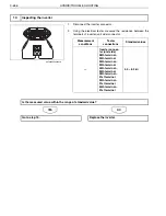
3
Inspecting the
DC high-volt-
age cable for
continuity 1
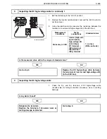
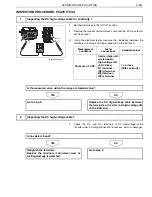
1. Set the starter key to the
"LOCK" position.
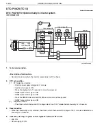
2. Remove the inverter terminal
block cover and the ECU box
terminal block cover.
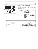
3. Using the electrical tester, mea-
sure the resistance between
the terminals of inverter and
high-voltage J/B (in the ECU
box).
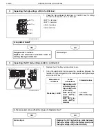
<Measurement conditions>
Starter key: LOCK
<Tester connections>
Inverter (high-voltage terminal)
–
High-voltage J/B (in ECU box)
P(1) terminal
–
INV(+) terminal
N(2) terminal
–
INV(-) terminal
<Standard values>
1 W or less (With continuity)
The mea-
sured value is
within the
range of stan-
dard value: Go
to YES.
The mea-
sured value is
not within the
range of stan-
dard value: Go
to NO.
Go to step 4.
Replace the
DC high-volt-
age cable
between the
terminals of
inverter and
high-voltage J/
B (in the ECU
box).
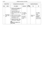
4
Inspecting the
DC high-volt-
age cable
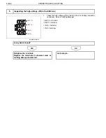
1. Check the P(+) and N(-) termi-
nals of DC high-voltage cable
(inverter side) for failing con-
nection (looseness, wear, or
melting damage).
Defect is
found: Go to
YES.
Defect is not
found: Go to
NO.
Retighten the
terminals.
Replace the
terminals if
abnormal wear
or melting
damage is
detected.
Go to step 5.

