HYBRID/TROUBLE SHOOTING
3–681
1.
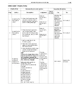
Install the system main resistor.
2.
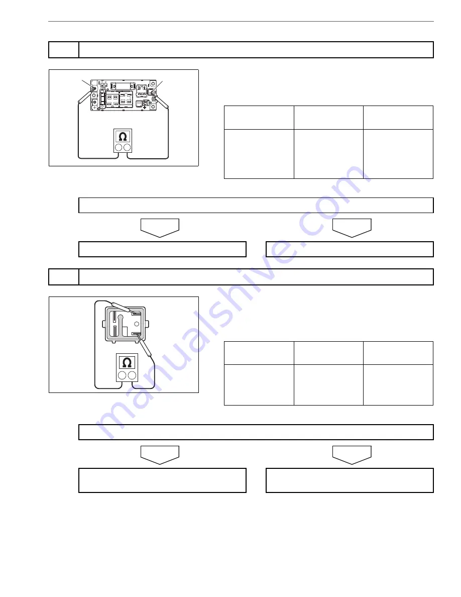
Using the electrical tester, measure the resistance between the
terminals of high-voltage J/B (in the battery pack)
NO
YES
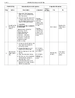
1.
Remove the SMR#1 from the high-voltage J/B (in the battery
pack).
2.
Using the electrical tester, measure the resistance between the
SMR#1 terminals.
NO
YES
3
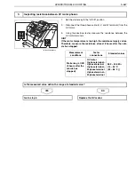
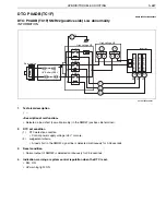
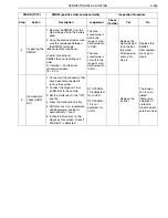
Inspecting the PN cable for short circuit
BATT OUT(-)
BATT IN(-)
SHTS03ZZZ0300446
Measurement
conditions
Tester
connections
Standard values
—
High-voltage J/B
(in battery pack)
BATT OUT(-) ter-
minal
–
BATT IN(-)
terminal
29.5
–
30.5
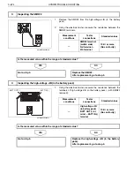
Is the measured value within the range of standard value?
Go to step 4.
Go to step 5.
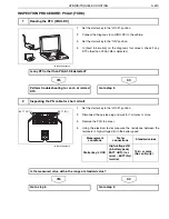
4
Inspecting the SMR#1
SHTS03ZZZ0300447
Measurement
conditions
Tester
connections
Standard values
—
SMR#1 terminal
(switch side)
3rd terminal
–
5th terminal
10 k
or more
(No continuity)
Is the measured value within the range of standard value?
Go to step 6.
Replace the SMR#1.
After replacement, go to step 6.

