HYBRID/TROUBLE SHOOTING
3–73
1.
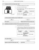
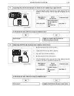
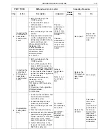
Using the electrical tester, measure the voltage between the 12th
terminal of PCU harness (24P) vehicle-side connector and the
ground.
NO
YES
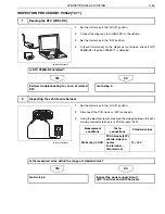
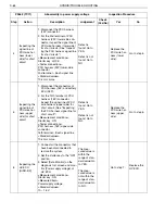
1.
Set the starter key to the "LOCK" position.
2.
Connect the PCU harness (24P) connector.
3.
Disconnect the HV ECU1 connector.
4.
Set the starter key to the "ON" position.
5.
Using the electrical tester, measure the voltage between the 54th
terminal of HV ECU1 connector and the ground.
NO
YES
5
Inspecting the vehicle wire harness for short circuit 2 (starter key signal circuit)
VEHICLE GND
SHTS03ZZZ0300055
Measurement
conditions
Tester
connections
Standard values
Starter key: ON
PCU harness (24P)
vehicle-side con-
nector
12th terminal
–
GND
Less than 1 V
Is the measured value within the range of standard value?
Go to step 6.
Repair or replace the wire harness.
(Starter key signal circuit)
6
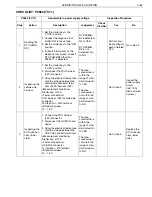
Inspecting the PCU wire harness (lower side) for short circuit
VEHICLE GND
SHTS03ZZZ0300056
Measurement
conditions
Tester
connections
Standard values
Starter key: ON
HV ECU1 connec-
tor
4th terminal
–
GND
Less than 1 V
Is the measured value within the range of standard value?
Go to step 7.
Replace the PCU wire harness (lower side).

